Download
1 / 20
200 likes | 318 Views
This comprehensive guide by Mike Pierno, titled "The Inverted Cone of Modern Industry," delves into the core principles of energy conversion and motion control. It covers various energy sources, including chemical, geothermal, solar, and nuclear, alongside essential mechanical systems. Readers will find valuable formulas, systems engineering concepts, and insights into hydraulic, pneumatic, and electrical energy applications. This resource is ideal for engineers, students, and industry professionals seeking to enhance their understanding of efficient energy use in modern technology.

E N D
Energy Conversion and Motion Control by Mike Pierno
ENERGY SOURCES AND CONVERSION ENVIRONMENTAL CHEMICAL GEO- THERMAL TROPIC SEAS WAVES WIND SOLAR FALLING WATER NUCLEAR COMBUSTION HEAT CONSTANT TEMP. REACTIONS REACTOR HEAT ISOTOPIC HEAT WATER TURBINE WAVE MOTOR PROPELLER AND SAIL SOLAR CELL M.H.D. GEN. INTERNAL COMBUSTION S.I. ENGINE DIESEL ENGINE THERMO- ELECTRIC STEAM ENGINE & TURBINE STIRLING ENGINE FUEL CELL & BATTERIES GAS TURBINE THERMIONIC
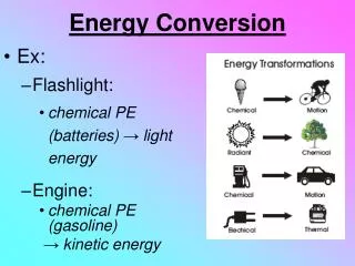
Energy Conversion Gasoline Energy (Chemical Energy) Belt or Chain S.I. Engine Combustion (Heat Energy) P.T.O. Shaft (Mechanical Energy) Gear Box or Power Train Indirect Drive Direct Drive Generator (Electrical Energy) Hydraulic Pump (Hydraulic Energy) Air Compressor (Pneumatic Energy) Hydraulic Power Electrical Power Pneumatic Power
ENERGY TECHNOLOGY FORMULAS • Work = Force x Distance W = F x D • Power = Work / Time P = W / T • Horsepower = HP 1HP = 746 Watts Watts = volts x amps • HP = Work / [Time(in seconds) x 550] • HP = Work / [Time (in minutes) x 33,000] • Efficiency = EF = (Output / Input) x 100 • Cubic Displacement Of An Engine S = Stroke • 3.14 x R2 x S x N N = Number of Cylinders • OHM’S LAW • ENGINE Torque = (5250 x HP) / RPM Horsepower = (Torque x RPM) / 5250 • LAB DYNAMOMETER HP = ( RPM’S x Torque) / 63,030 I R V
MOTION CONTROL Motion Control is the distribution and control of energy that has been converted from its original state into either mechanical, fluid (hydraulic, pneumatic), or electrical energy to do useful work.
SYSTEMS ENGINEERING TECHNOLOGY I. Mechanical II. Fluids III. Electrical LOAD/WORK TO BE DONE PRIME MOVER
SYSTEMS ENGINEERING TECHNOLOGY I. Mechanical A. simple machines (physical science) II. Fluids A. hydraulics fundamentals (physical science) B. pneumatics fundamentals (physical science) III. Electrical A. electricity fundamentals (physical science) LOAD/WORK TO BE DONE PRIME MOVER
SYSTEMS ENGINEERING TECHNOLOGY I. Mechanical A. simple machines (physical science) 1. COMPONENTS 2. MECHANICAL SYSTEMS II. Fluids A. hydraulics fundamentals (physical science) 1. Components 2. Circuits B. pneumatics fundamentals (physical science) 1. Components 2. Circuits III. Electrical A. electricity fundamentals (physical science) 1. Components 2. Circuits LOAD/WORK TO BE DONE PRIME MOVER
MECHANICAL TRANSMISSION FORMULAS Inclined Plane F = (R x H) / L F= Force R= Resistance H= height of ramp L= length of ramp Screw M.A. = (2 x 3.14 x R)/P P= Pitch Pulley and Belt N = V/(3.14 x D) N= R.P.M Calculations V= Velocity in ft./min. Gear T = D.P. x P.D. T= Teeth Calculations D.P. = T/P.D. D.P. = dimetrical pitch P.D. = T/D.P. Speed S2 = S1 x ( T1/ T2) S1 = Speed of the first shaft in train Reduction Calculations S2 = Speed of the last shaft in train (Changing Speed) T1 = Product of teeth on driver gears T2 = Product of teeth on all given gears Lever L/I = R/E L= length of effort arm I = length of Resistance arm R= Resistance E= Effort Force Mechanical Advantage M.A.= R/E Wheel & Axle L/I = R/E L= Radius of Wheel I= Radius of axle R= Resistance E= Effort Pulley E = R/N E= Effort N=Number of Strands R= Resistance
FLUID POWER FORMULAS The pressure, force and area relationship is illustrated as shown below To determine the speed of a cylinder when the size and gpm to aid in remembering the equations. are known: Speed (inches per min.) F = Force in lbs. Force Triangle Speed = (GPM x 231) / piston area P = Pressure in lbs./sq. in. A = Area in sq. in. F = P x A P = F/A A = F/P To determine flow requirements of given speed of cylinder GPM = Piston Area x Speed (in,/min.) / 231 Hydraulic motors: To determine the gpm of a given speed To compute piston area: 3.14 x R2 1 Gal. = 231 cubic inches GPM= {Speed (Rpm) x Displacement (Cu. In./rev.)} / 231 Volume of cylinder: 3.14 x R2 x L To determine the horsepower to drive a hydraulic system, based on the efficiency of 80% HP = GPM x PSI x .000583 GPM = (area x distance x 60) / (231 x time in seconds) Cu. In./min = GPM x 231 F P A
ELECTRICITY FORMULAS POWER LAW OHM’s LAW Formulas in Common Use Ohm’s law for dc circuitsResistance I = V / R P = I2R In Series RT = R1 + R2 + R3 V = IR I = (P / R) In Parallel 1/ RT = 1/R1 + 1/R2 + 1/R3 R = V / I V = (PR) P = IV R = P / I2 Two Resistors in Parallel I = P / V P = V2 / R RT = R1 R2 / R1 + R2 V = P / I R = V2 / P Equal Resistors in Parallel RT = R/N R = any one resistor N = number of resistors in parallel P V I V I R
“MISSING MIDDLE” “HIGH TECH/ BUSINESS SERVICES” “RETAIL TRADE/ SERVICES” HIGH WAGE/HIGH SKILL LOW WAGE/LOW SKILL
“MISSING MIDDLE” MILL BASED/SMOKESTACK INDUSTRIES “HIGH TECH/ BUSINESS SERVICES” “RETAIL TRADE/ SERVICES” HIGH WAGE/HIGH SKILL LOW WAGE/LOW SKILL
Energy Conversion and Motion Control by Mike Pierno