Vapor Intrusion Evaluation Strategy and Modeling Developments
260 likes | 419 Views
Vapor Intrusion Evaluation Strategy and Modeling Developments. Robert Ettinger Geosyntec Consultants California Industrial Hygiene Council 16 th Annual Conference San Diego, CA December 4 – 6, 2006. Timeline for the Vapor Intrusion Pathway. Radon Intrusion & Vapor Diffusion studies.

Vapor Intrusion Evaluation Strategy and Modeling Developments
E N D
Presentation Transcript
Vapor IntrusionEvaluation Strategy and Modeling Developments Robert Ettinger Geosyntec Consultants California Industrial Hygiene Council 16th Annual Conference San Diego, CA December 4 – 6, 2006
Timeline for the Vapor Intrusion Pathway Radon Intrusion & Vapor Diffusion studies OSWER Draft Guidance CA, NY, NJ State Guidance Development Air-Superfund Guidance Draft RCRA EI Supplemental Guidance MA State Guidance J&E Model Revised OSWER Guidance ASTM RBCA Standard Response to Comments RCRA EI Guidance 1980’s 2002 1992 1993 2004 2005 2007 2001 1989 1991 1999 1994 MEW Hillside School Hill AFB Endicott CDOT Redfields
Vapor Intrusion Evaluation Strategy • Utilize Tiered Approach • Data collection and analysis increase in higher tiers • Target Indoor Air Levels • Risk-based levels, PELs, background • Media Sampled & Locations • Groundwater, soil gas, indoor air • Near, next to, or beneath buildings • Other Data • Geologic characterization, building characteristics • Modeling Options • Empirical, screening level, site-specific • Corrective Action Selection
Target Indoor Air Levels • Typically, indoor air target levels based on risk-based concentrations developed using EPA risk methodology • Need to consider • Target risk level • Occupational standards • Background concentrations Example Target Indoor Air Levels
Site Characterization What data are best to characterize vapor intrusion pathway? • Indoor Air • Groundwater • Soil • Soil Gas
Indoor Air Sampling • Indoor air sampling may seem to be a direct assessment approach, but is typically conducted during higher tier of investigation • Several challenges to indoor air sampling • Occupant disruption • Temporal and spatial variability • Background effects • May more practical to collect indoor air samples in occupational setting • Indoor air sampling guidance • Sample collection techniques • Analytical methods • Building survey examples
Source Characterization • Groundwater • Henry’s Law to evaluate partitioning • Mass transport limitations due to vertical concentration gradients in saturated zone • Soil • Gas-water and water-solid partitioning • Uncertainty in accuracy of partitioning equation • Soil Gas • Soil gas results can resolve uncertainty associated with groundwater or soil data • Typically provide better source characterization for vapor intrusion pathway.
Soil Gas Sample Location • Current regulatory focus on appropriate sampling locations • Near source • Exterior to building • Sub-slab • Soil gas profile may be affected by building • More significant for biodegradable compounds
Soil Gas Sampling • Soil gas sampling methods not as uniform as groundwater sampling methods, but approaches to meet investigation data quality objectives are available
Sub-Slab Soil Gas Sampling • Requires building access • Methods developed to limit intrusiveness (DiGiulio, 2004)
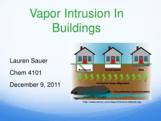
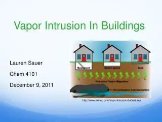
Vapor Intrusion Modeling • Mixing in Breathing Zone • Convective Transport into Bldg • Diffusive Transport toBreathing Zone • Impacted Soil and/or Groundwaterin Equilibrium with Soil Gas Risk is proportional to (a) x (Csoil gas)
Empirical Attenuation Factor (Dawson, 2004)
Johnson-Ettinger (1991) Attenuation Factor • Secondary Parameters • Deff = fn(H, Dwater, Dair, qT, qw)for each layer • LT = S(Li) • Qsoil = fn(k, DP, rcrack, zcrack, xcrack) • Primary Parameters • Deff = Effective diffusion coefficient • LT = Depth to source • AB = Building area in contact with soil • QB = Building ventilation rate • Qsoil = Soil gas convection rate • Dcrack = Eff. diff. coeff. through cracks • Lcrack = Crack thickness • h = Building crack factor J & E Model has dozens of input parameters, how much data is required to use?
One-dimensional vertical transport Steady state conditions No preferential pathways Uniform mixing within building Slab on grade or basement construction No biodegradation Homogeneous vadose-zone Constant source concentration No gas generation (e.g., municipal waste) No barometric pumping Common Screening Model Assumptions Prior to using model results, you need to ensure that model assumptions and site conditions are consistent
Constrained Model Use • Many problems with vapor intrusion modeling associated with improper inputs • Updated EPA spreadsheets will limit values allowed for inputs • Constraints based on Johnson, 2002
Biodegradation Modeling • Methods to model vadose zone biodegradation have been developed • Johnson et. al., 1999 – Dominant Layer Model • Abreu and Johnson, 2004 – 3D Numerical Model • Typically, additional site investigation data will be necessary to conduct biodegradation modeling • Soil gas concentration profile data • Analysis of biodegradation indicators (O2 , CO2) • Tracer compounds • Consider use of soil vapor profile data
Mixing in Breathing Zone Convective Transport into Building Diffusive Transport Source Partitioning Screening Level Biodegradation Model(Johnson, et al., 1999) • Requires additional data collection for bio indicators • Calibrate model with site soil gas data to determine biodegradation parameters • Reduce a by factor of 10 – 1000 Biodegradation Zone VOCs
Three-Dimensional Numerical Model(Abreu and Johnson, 2005) • Model Description • 3-D vadose zone F&T model • Evaluate building type, source scenarios, and biodegradation kinetics • Model Results • Impact of biodegradation • Significance of lateral migration
Soil gas profile sampling points Soil surface O2 CO2 VOCs Investigation Approach for Complex Sites • Soil gas profile data recommended to assess biodegradation • Biodegradation significantly affects petroleum compound vapor migration • No common approach to use soil gas profile data to quantitatively evaluate vapor intrusion pathway
Soil Gas Profile Data • Soil gas profile underneath building may be different than that outside building footprint. • May need to assess potential exposure scenarios • Evaluate soil gas data to address uncertainty in sub-surface transport (diffusion and biodegradation) • Reassess vapor intrusion evaluation from subsurface source (include convection and ventilation effects) Soil gas samples
Choice of Remedy • Active Remediation • Institutional Controls • Engineering Controls • “Radon System” • HVAC Modifications • Sealing • Filtration • Building Design (Brownfields)
Mitigation Options: Radon Sump http://www.bre.co.uk/radon/reduce.html
Summary • Selection of appropriate target levels is key factor in vapor intrusion assessment. • Site investigation methods require careful planning. • When modeling, assess whether site conditions are consistent with conceptual model assumptions and input parameters are reasonable. • Corrective action planning may reduce scope of vapor intrusion investigation. • Consider multiple lines of evidence to support conclusions. A balance of modeling and monitoring is typically appropriate.