Repair Sharing
Repair Sharing. [P8H61][REV 3.0][MIBF00] : No VCORE The Initial Problem Analysis: 1 : Visually check MB slot for damage. Check front and back of the board for line breaks. 2: Check SX1 if it has 32.768 KHz or not. Check POU37 PIN2 +3VSB and OR1 PIN1 +3VSB_ATX are normal.

Repair Sharing
E N D
Presentation Transcript
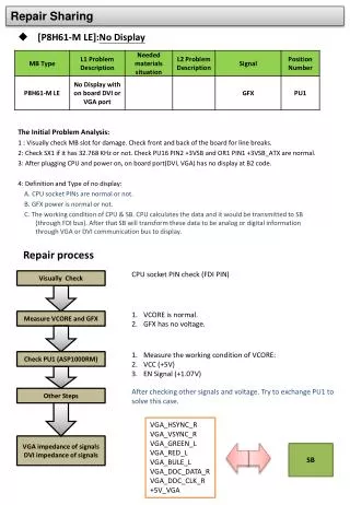
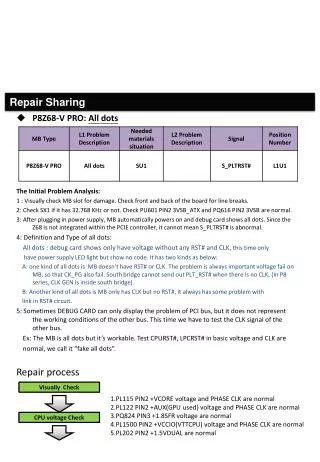
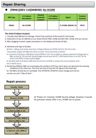
Repair Sharing • [P8H61][REV 3.0][MIBF00]: No VCORE • The Initial Problem Analysis: • 1 : Visually check MB slot for damage. Check front and back of the board for line breaks. • 2: Check SX1 if it has 32.768 KHz or not. Check POU37 PIN2 +3VSB and OR1 PIN1 +3VSB_ATX are normal. • 3: After plugging in power supply and power on, the debug card shows all dots. • 4: Definition and Type of all dots: • All dots : debug card shows only have voltage without any RST# and CLK, this time only • have power supply LED light but show no code. It has two kinds as below: • A: one kind of all dots is MB doesn’t have RST# or CLK. The problem is always important voltage fail on MB, so that CK_PG also fail. South bridge cannot send out PLT_RST# when there is no CLK, (In P8 series, CLK GEN is inside south bridge). • B: Another kind of all dots is MB only has CLK but no RST#, it always has some problem with • link in RST# circuit. • 5: Sometimes DEBUG CARD can only display the problem of PCI bus, but it does not represent the working conditions of the other bus. This time we have to test the CLK signal of the other bus. • Ex: The MB is all dots but it’s workable. Test CPURST#, LPCRST# in basic voltage and CLK are • normal, we call it “fake all dots”. • Repair process Visually Check At “Power on” moment, VCORE has the voltage. However, it would be pull down slowly. After 5 sec, VCORE has no power. Measure VCORE Measure for VCORE(Phase) is short to GND or not Measure for +12V_4PIN is short to GND or not Measure for VCORE(Phase) is short to +12V_4PIN or not
Measure the working condition of VCORE: VCC (+5V) EN Signal (+1.07V) Check PU1 (ASP1000RM) Other Steps It’s fail to exchange ASP1000RM IC. Further check, PQ2 MOSFET has abnormal wave. First suspect that is caused form PU2, but it’s useless to exchange it. Try to remove all related components, still has this abnormal waveform. Find the back of MB has a resistor and also connects with this signal. Try to remove it and measure it’s impedance. Find it is abnormal. After replacing PR73, VCORE is normal. PR73 (P_VCORE_ISEN2P_10)