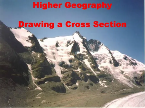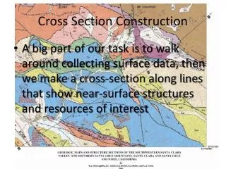
Constructing a Geological Cross Section
Constructing a Geological Cross Section. Select a section line Construct a topographic profile along the line of section Transfer contacts from the map to the topographic profile Project dip data into the cross section line Calculate and plot apparent dips on the topographic profile

Constructing a Geological Cross Section
E N D
Presentation Transcript
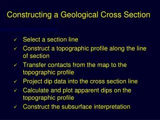
Constructing a Geological Cross Section • Select a section line • Construct a topographic profile along the line of section • Transfer contacts from the map to the topographic profile • Project dip data into the cross section line • Calculate and plot apparent dips on the topographic profile • Construct the subsurface interpretation
Selecting a Section Line • Identify regional structural trends • Draw section line perpendicular to regional structural trends and through areas that best depict the structure • May need more than one section line • Draw sections through area(s) with the best structural control • Most reliable contacts • Nearby structural data
Step 1: Mark the intersection of each topographic contour line with the section line
Step 2: Graph the elevation of each point in its appropriate position
Use logical, whole number increments for the vertical scale. Step 3: Connect the Dots
Transferring Contacts from the Map to the Topographic Profile Step 1: Mark the intersection of each contact, fault or unconformity with the section line
Transferring Contacts from the Map to the Topographic Profile Step 1: Mark the intersection of each contact, fault or unconformity with the section line Step 2: Transfer the location of each contact, fault or unconformity marked on the section line to the topographic profile
Projecting Dip Data into the Cross Section Line • Step 1: Identify which dip data you will use • Use data that occurs in a narrow band along either side of your section line • Projection distance is inversely proportional to structural complexity
Projecting Dip Data into the Cross Section Line • Step 2: Project the data into the cross section line • Project parallel to strike to the point where the projection line intersects the section line • Do not project across formation boundaries, faults or unconformities • Intuitively use data close to the section, even if it doesn’t project into the section line • e.g. contacts striking parallel to the section line will appear horizontal in the section plane
Projecting Dip Data into the Cross Section Line Step 3: Transfer the location of each projected dip data point to the topographic profile(tadpole)
Calculate Apparent Dips • Use apparent dip nomogram to determine the apparent dip of each data point projected into the cross-section plane • Page 83
Plot Apparent Dips on the Topographic Profile Step 1: At each apparent dip data point, use a protractor to measure down from horizontal, the angle equal to the calculated apparent dip Step 2: Draw in the apparent dip symbol at the appropriate angle, and in the appropriate direction • These angles must be drawn precisely, not just eyeballed
Construct the Subsurface Interpretation • Remember: A cross section is an interpretation! • Honor your data • Uniform layer thickness unless you have good evidence to the contrary • Remember squishy units are more likely to change thickness • Dip angles may only be valid for a short distance • They don’t continue forever with increasing depth
Principles of Cross Section Construction • Viability Criteria • Assume areas and lengths of rock layers remain constant during deformation • True under plane strain conditions where temperatures are < 250˚ C • Each unit lies at a unique regional elevation when not uplifted by faulting or intrusions • Faults must have realistic geometries and kinematics • No gaps or overlaps between fault blocks • No changes in slip sense • Realistic displacement gradients
Principles of Cross Section Construction • Admissibility Criteria • Interpret in a manner that is consistent with established regional structural styles • But, you can still discover something new! • Do not add complexity where it is not supported by the data • Occam’s Razor • (14th Century Franciscan Friar and logician, William of Ockham) • Usually, the simplest answer is the best answer
Evolution of Structural Interpretations 1960’s 1970’s 1980’s
East Grass Creek Seismic Profile Mitra and Mount (1998)
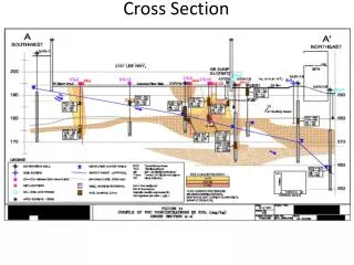
East Grass Creek Cross Section Mitra and Mount (1998)
Hamilton Dome Cross Section Mitra and Mount (1998)
Rangely Anticline Cross Section Mitra and Mount (1998)
Willow Creek Cross Section Mitra and Mount (1998)
Common Cross Section Errors • Contacts on map don’t match those on the section line • Ignoring dip data • Topography-induced folding • Blank spaces underground • Incorrect stratigraphic sequence • Mismatch between intersecting section lines • Appendix 3 page 89 for more Essentials