Download
1 / 43
430 likes | 575 Views
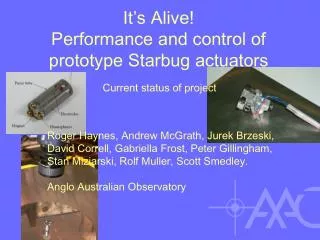
It’s Alive! Performance and control of prototype Starbug actuators. Current status of project. Roger Haynes, Andrew McGrath, Jurek Brzeski, David Correll, Gabriella Frost, Peter Gillingham, Stan Miziarski, Rolf Muller, Scott Smedley. Anglo Australian Observatory.

E N D
It’s Alive!Performance and control of prototype Starbug actuators Current status of project Roger Haynes, Andrew McGrath, Jurek Brzeski, David Correll, Gabriella Frost, Peter Gillingham, Stan Miziarski, Rolf Muller, Scott Smedley. Anglo Australian Observatory
Deployable Payloads with Starbug Concept and applications Andrew McGrath, Roger Haynes. Anglo Australian Observatory
Three questions… • What is Starbug? • Why use it? • Where’s the technology at now?
What is Starbug? • Starbug is a focal plane positioning concept • Microrobotic actuators patrolling across a physical surface to position payloads in a telescope’s focal surface • Simultaneous motion of actuators • Configuration time independent of number of buttons • Highly redundant architecture • No large mechanisms
Why use it? • Need to deploy and manipulate payloads within the focal plane • Historically • Manually positioned • Robotic arms • Payloads supported on arms • Payloads supported on magnetic buttons on a field plate • Greater number of resolution elements per field (Larger telescopes, Adaptive optics) • Sparse distribution of interesting targets within field • Detector-limited instrumentation • Reformatting the focal plane for efficiency • Fibre-fed MOS • IFUs • Image slicers • Deployable sub-field imagers • etc.
Starbug Advantages Field configuration time • Simultaneous activation of actuators • Configuration time independent of, or reducing with bug numbers • c.f. pick-and-place, where time is proportional to pickoff numbers • e.g. 2dF takes ~1hr with 400 fibres; same bug numbers and plate size with bug speed of 0.5mm/s expect 2 mins.
Starbug Advantages Microtracking • Adjust field configuration during an observation • Accommodate variation in plate scale across FoV during tracking (continuously or in discrete steps) • e.g. 0.5”/hr at extremes of FMOS 30’ FoV, >2”/hr for 2dF • More important for finer spatial resolutions (AO, ELT) • Otherwise need multiple observations
Starbug Advantages Positioner size and mass • Starbug decouples size of robotic components from size of focal surface • No plate exchange • c.f. pick-and-place, requiring robot to span positioning range and possibly exchange focal plates
Starbug Advantages Redundancy • Largely independent actuators • Fewer single-point failure modes • Graceful system degradation with failures
Starbug Advantages Scalability • Scalable to different focal surfaces merely by changing field plate • Scalable in pickoff numbers
Starbug Advantages Cryo accessibility • Microrobotic technologies (e.g. piezo) can avoid lubricants, are vacuum-friendly, and operate at low temperatures • No large mechanisms to design for low temps
Starbug Advantages Instrument upgrade path • High degree of planned upgrading and future-proofing • Modular architecture, easy to upgrade components • Ideal prototyping environment on ‘live’, facility-class instrument
There is a variety of classes of instrument that suit the characteristics of Starbug. We now know what Starbug is.We know a bit about its characteristics.
Discrete object fibre-fed MOS • Somewhat like 2dF/OzPoz/6dF except Starbug actuators in place of passive bugs with pick-and-place • Easier cryo due to small Starbug mechanisms and minimal support equipment to be cooled OzPoz button Starbug equivalent
Fibre-fed Deployable IFU Pickoffs (dIFUps) • Similar to FLAMES dIFUps (discrete subfields), or tileable for arbitrary contiguous area coverage
Subfield Imaging • via image relay (mirrors and lenses) • via coherent imaging bundles(poster 6273-148, R.Haynes et al. “Advances in IR and imaging fibers for astronomical instrumentation”) • via active imaging payloads • bare detectors on bugs
Relayed Image IFU MOS • As for subfield imaging, but relay feeds spectrograph(s), KMOS-style Simulated Starbug image relay MOS field configuration, with 178 out of 200 bugs allocated to targets from 800 randomly distributed targets on a 300mm focal surface.
Active Science Payloads • APDs, or other light sensors for photometry • Deployable microspectrographs • Detector/filter combinations • Tunable filters • Detector arrays
Subfield Correction • High levels of AO correction ‘challenging’ for wide field • Starbug may enable multi-object AO with low-order correction applied at the telescope level, across the field, and higher order correction applied locally by active bug payloads to the relevant subfields (cf Falcon, Hammer et al., OPM & LAM) • May also be possible todo bug-based secondorder (residual) correctionto subfields for aO orADC errors • Share the difficulty between global and local correction
Telescope infrastructure payloads • Guide probes • Wavefront sensors for active mirror control • Eliminates need for ‘engineering field’
The Multi “Multi-Object-Instrument” Instrument • Bug infrastructure decoupled from payloads • No need for bug ‘standardisation’ on a single plate • Simultaneous observing with mixed payload types • Precedents: • FLAMES (discrete objects + dIFUps) • WFMOS (different fibres to different spectrograph types)
Where’s the technology at now? We now know what Starbug is.We know what it’s good for.
But surely it’s science fiction? (The Starbug name comes from the name of a spacecraft in a British comedy science fiction television show called Red Dwarf. It crashed frequently.)
Actuator development Concept formed at AAO 2000-2002 arising from AAO heritage of fibre positioning technologies 2dF – 6dF/OzPoz - Echidna
Technology Readiness Level NASA terminology • TRL 1 Basic principles observed and reported • TRL 2 Technology concept and/or application formulated • TRL 3 Analytical and experimental critical function and/or characteristic proof-of-concept • TRL 4 Component and/or breadboard validation in laboratory environment • TRL 5 Component and/or breadboard validation in relevant environment • TRL 6 System/subsystem model or prototype demonstration in a relevant environment (ground or space) • TRL 7 System prototype demonstration in a space environment • TRL 8 Actual system completed and “flight qualified” through test and demonstration (ground or space) • TRL 9 Actual system “flight proven” through successful mission operations
Technology Readiness Level NASA terminology • TRL 1 Basic principles observed and reported • TRL 2 Technology concept and/or application formulated • TRL 3 Analytical and experimental critical function and/or characteristic proof-of-concept • TRL 4 Component and/or breadboard validation in laboratory environment • TRL 5 Component and/or breadboard validation in relevant environment • TRL 6 System/subsystem model or prototype demonstration in a relevant environment (ground or space) • TRL 7 System prototype demonstration in a space environment • TRL 8 Actual system completed and “flight qualified” through test and demonstration (ground or space) • TRL 9 Actual system “flight proven” through successful mission operations Pick-and-place is here
Technology Readiness Level NASA terminology • TRL 1 Basic principles observed and reported • TRL 2 Technology concept and/or application formulated • TRL 3 Analytical and experimental critical function and/or characteristic proof-of-concept • TRL 4 Component and/or breadboard validation in laboratory environment • TRL 5 Component and/or breadboard validation in relevant environment • TRL 6 System/subsystem model or prototype demonstration in a relevant environment (ground or space) • TRL 7 System prototype demonstration in a space environment • TRL 8 Actual system completed and “flight qualified” through test and demonstration (ground or space) • TRL 9 Actual system “flight proven” through successful mission operations Echidna is here
Technology Readiness Level NASA terminology • TRL 1 Basic principles observed and reported • TRL 2 Technology concept and/or application formulated • TRL 3 Analytical and experimental critical function and/or characteristic proof-of-concept • TRL 4 Component and/or breadboard validation in laboratory environment • TRL 5 Component and/or breadboard validation in relevant environment • TRL 6 System/subsystem model or prototype demonstration in a relevant environment (ground or space) • TRL 7 System prototype demonstration in a space environment • TRL 8 Actual system completed and “flight qualified” through test and demonstration (ground or space) • TRL 9 Actual system “flight proven” through successful mission operations Starbug is here
First steps Demonstration of feasibility with ‘Kickbot’ as displayed at SPIE Glasgow 2004 • Drive: Impulse • Footprint: < 10mm • Step size: < 1um • Speed: a few mm/minute • Orientation: up to ~20º • No rotation • Microtracking: Yes • Payload potential: Good • Electronics: 4 wire, high V, low I • Drive frequency: Low
First steps • Subsequent development as part of Opticon FP6 JRA5 ‘Smart Focal Planes’ group • Targeted at MOMSI – multiobject spectroscopy for ELT • Goal performance specifications: • footprint <10mm • operate under closed loop control • positioning accuracy ~1m or better • accommodate microtracking to correct for field distortions (e.g. atmospheric refraction effect) • orientate payload to align optical relay pick-offs • patrol freely over a possibly curved focal surface • varying gravitational orientation from 0-90º • low temperature and vacuum environment.
Elli • Drive: Resonant • Footprint: 26mm long • Step size: ? • Speed: Fast • Orientation: 0-90º • Limited rotation • Microtracking: Limited • Payload potential: ? • Electronics: 4 wire, low V, high I • Drive frequency: kHz
Res 1-5 • Drive: Resonant • Footprint: 10mm • Step size: <1um • Speed: Fast • Orientation: 0-90º • Rotation • Microtracking: Yes • Cryogenic operation: Good • Payload potential: Good • Electronics: 2 wire, low V, high I • Drive frequency: 100s kHz
Res J • Drive: Resonant • Footprint: ~ 6mm • Step size: ~ 0.8um • Speed: ~ 0.7mm/s • Orientation: 0-90º • Rotation • Microtracking: Yes • Cryo operation: Slower 0.2mm/s • Payload potential: Good • Electronics: 4 wire, high V, low I • Drive frequency: kHz
Impulse • Drive: Inertial stick-slip • Footprint: ~10mm • Step size: Failed • Speed: Failed • Orientation: No • Rotation in principle • Microtracking: in principle • Cryo operation: ? • Payload potential: ? • Electronics: 4 wire, low V, high I • Drive frequency: 10-100s Hz
Stepper • Drive: Inertial stick-slip • Footprint: ~16mm • Step size: <1um • Speed: Not measured • Orientation: ? • Rotation: in principle • Microtracking: Yes • Cryo operation: ? • Payload potential: Good • Electronics: 4 wire, low V, high I • Drive frequency: 100s Hz
Tri-Ped (Bi – Ped) • Drive: Inchworm • Footprint: ~18mm • Step size: <1um • Speed: Not measured • Orientation: ? • Rotation: Yes • Microtracking: Yes • Cryo operation: ? • Payload potential: Good • Electronics: 8 wire, high V, low I • Drive frequency: 100s Hz
Crowd Surfer • Drive: Travelling wave • Footprint: Minimum ~ 6mm • Step size: >1um • Speed: ~0.5mm/s • Orientation: ? • Rotation: in principle • Microtracking: in principle • Cryo operation: ? • Payload potential: Very good • Electronics: Complex, high V, low I • Drive frequency: 100s Hz
Metrology and control • Camera imaging focal surface (FPI) • 1/30th Pixel centoiding (3 sigma) demonstrated with Starbug and FMOS – Better possible? • Closed loop control (Res-J) 10um (feedback control limit)
Metrology and control • On-telescope FPI can be convenient by imaging through reflection in primary, camera mounted to spider • Imagery tested using 2dF on AAT • 1/20th pixel easily achieved
Conclusions • Starbug is a focal plane positioning concept using microrobotic actuators patrolling simultaneously across a surface to enable wide-field multiobject observation • The concept is potentially cheap, light and robust compared with other positioning technologies, with short field reconfiguration times • Starbug accommodates • Dynamic field reconfiguration (microtracking) • Cryogenic and vacuum operation • Active or passive payloads • Local (subfield) correction • Candidate actuator technologies have already been developed, reaching TRL ~ 3
Drive: Resonant • Footprint: ~ 6mm • Step size: ~ 0.8um • Speed: ~ 0.7mm/s • Orientation: 0-90º • Rotation • Microtracking: Yes • Cryo operation: Slower 0.2mm/s • Payload potential: Good • Electronics: 4 wire, high V, low I • Drive frequency: kHz