Download
1 / 144
1.9k likes | 2.91k Views
Acoustic Sensors and Actuators. Chapter 7. Introduction. Acoustics - “Sound” and its effects Frequencies - 0 to over 1 GHz Audio: 20Hz to 20 kHz Ultrasound: 20 kHz and up Infrasound: 0 to 20 Hz. Sound: Longitudinal pressure waves. Introduction.

E N D
Acoustic Sensors and Actuators Chapter 7
Introduction • Acoustics - “Sound” and its effects • Frequencies - 0 to over 1 GHz • Audio: 20Hz to 20 kHz • Ultrasound: 20 kHz and up • Infrasound: 0 to 20 Hz. • Sound: Longitudinal pressure waves
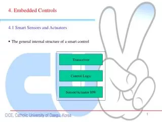
Introduction • As a means of sensing and actuation, sound waves have developed in a number of directions. • Use of sound waves in the audible range for sensing of sound (microphones, hydrophones, pressure sensors) • Actuation using speakers, ultrasonic motors. • Sonar – the generation and detection of acoustics (including infra and ultrasound) in the ocean • Testing of materials, material processing and in medicine.
Acoustic waves • Sound waves are longitudinal elastic waves. • The pressure wave as it propagates, changes the pressure along the direction of its propagation. • Example: acoustic waves, impinging on our eardrums will push or pull on the eardrum to affect hearing. • Any wave, including acoustic waves have three fundamental properties: Frequency, wavelength and speed of propagation
Acoustic waves • The frequency, f, of a wave is the number of variations of the wave per second. • Normally defined for harmonic waves and is understood to be the number of cycles/second of the harmonic (sinusoidal for example) wave. • For example, if we were to count the number of crests in an ocean wave passing through a fixed point in one second, the result would be the frequency of the wave.
Acoustic waves • Wavelength, l, is the distance a wave propagates in one cycle. • In the example of the ocean wave the wavelength is the distance between two crests (or two valleys) • Velocity, c, of the wave is the speed with which the front of the wave propagates and, as indicated above, is frequency dependent. • These three quantities are related as: l = c/f
Acoustic waves • Waves can be transverse waves, longitudinal waves or a combination of the two. • Transverse waves are those waves which cause a change in amplitude in directions transverse to the direction of propagation of the wave. • Example: a tight string vibrates perpendicular to the length of the string. The wave itself propagates along the string. • The wave propagates away from the source, in all directions.
Acoustic waves • Generation of longitudinal waves: • Example: piston in a tube • Example: diaphragm in air • Effect: changes in volume cause changes in pressure. These propagate - give rise to the wave.
Acoustic waves - speed • The speed of an acoustic wave is directly related to the change in volume and the resulting change in pressure • 0 is the density of the undisturbed fluid, • V is the change in volume, • p is the change in pressure • V is the volume
Acoustic waves - speed • In gasses, this simplifies to the following • 0 is the density of the undisturbed fluid, • is the ratio of specific heats for the gas, • p0 is the undisturbed gas pressure • Thus, the speed of acoustic waves is material, pressure and temperature dependent
Acoustic waves - theory • Assuming a harmonic longitudinal wave of frequency f, it may be written in general terms as: • p is pressure in the medium, • P0 the pressure amplitude of the wave • k is a constant. • The wave propagates in the x direction • f is the angular frequency
Acoustic waves - theory • The amplitude of the wave is: • ym is the maximum displacement of a particle during compression or expansion in the wave. The constant k is called the wave number or the phase constant and is given as:
Acoustic waves - theory • Waves carry energy. • A shockwave (earthquake) can cause damage • A loud sound can hurt our ears. • A wave is said to be a propagating wave if it carries energy from one point to another. • The wave can propagate in an unbounded medium with or without attenuation (losses). • Attenuation of a wave depends on the medium • Attenuation reduces the amplitude of the wave. • Attenuation of waves is exponential
Acoustic waves - theory • Attenuation constant is defined for each material • The amplitude of the wave, as it propagates, changes as follows Attenuation causes loss of energy as the wave propagates Dissipates energy of the wave
Acoustic waves - theory • When a propagating wave encounters a discontinuity in the unbounded space (an object such as a wall, a change in air pressure, etc) part of the wave is reflected and part of it is transmitted into the discontinuity. • Reflection and transmission occur at any discontinuity • These reflected and transmitted waves may propagate in directions other than the original wave. • Transmission causes refraction of the wave.
Acoustic waves - theory • The reflected wave is reflected at an angle equal to the angle of incidence (r=i) • The transmitted wave propagates in the material at an angle qt which is equal to: • c2 is the speed of propagation of the wave in the medium into which the wave transmits • c1 the speed in the medium from which the wave originates
Acoustic waves - theory • The reflected waves propagate in the same medium as the propagating wave • Interfere with the propagating wave. • Their amplitude can add (constructive interference) or subtract (destructive interference). • The net effect is that the total wave can have amplitudes smaller or larger than the original wave. • This phenomenon leads to the idea of a standing wave.
Acoustic waves - theory • Interference will cause some locations in space to have lower amplitudes (or zero) while others will have amplitudes larger than the incident wave. • This is called a standing wave because the locations of zero amplitudes (called nodes) are fixed in space as are the locations of maxima. • Figure 7.5 shows this and also the fact that the nodes of the standing wave are at distances of /2 while maxima occur ate/4 on either side of a node.
Standing waves • Example of standing waves: vibrating tight strings • reflections occur at the locations the strings are attached. • This vibration at various wavelengths, and its interaction with the air around accounts for the music we perceive when a violin plays.
Acoustic waves - theory • Scattering is reflection of the waves in all directions due to anything in the path of the waves. • Dispersion is the propagation of various frequency components at different speeds causing distortion in the received sound wave. • Wave impedance or acoustic impedance is the product of density and velocity: Z = r0c
Microphones • Microphones are sound sensors (really - transient pressure sensors) • Speakers are sound actuators • The first microphones and speakers (or earphones) were devised and patented for use in telephones. • Alexander Graham Bell patented the first variable resistance microphone in 1876
The carbon microphone • First practical microphone was invented by Edison • The solution was replaced with carbon or graphite particles –the carbon microphone. • In continuous use in telephones ever since • Rather poor performance (noise, limited frequency response, dependence on position and distortions) • An “amplifying” device (can modulate large currents) and hence its use in telephones. • It is still being used, to drive an earpiece directly without the need for an amplifier.
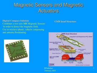
The magnetic microphone • Better known as the moving iron microphone, together with its cousin, the moving iron gramophone pickup have largely disappeared and have been replaced by better devices. • Its structure is quite common in sensors (we have seen a similar device used as a pressure sensor in chapter 6 - the variable reluctance pressure sensor). • The basic structure is shown in Figure 7.10.
The magnetic microphone • Operation: the armature (a piece of iron that moves due to the action of sound or a needle in the case of a pickup) decreases the gap towards one of the poles of the iron core. • This changes the reluctance in the magnetic circuit. • If the coil is supplied with a constant voltage, the current in it depends on the reluctance of the circuit. • Hence the current in the coil depends on sound level
Moving coil microphone • Known as the dynamic microphone. • The first microphone that could reproduce the whole range of the human voice • Has survived into our own times even though newer, simpler devices have been developed and will be discussed shortly. • Operation is based on Faraday’s law: Given a coil moving in the magnetic field, it produce an emf :
Moving coil microphone • Fundamentally the same as a common loudspeaker • Any small loudspeaker can serve as a dynamic microphone • The dynamic microphone, just like the moving iron microphone is a dual device capable of serving as a loudspeaker or earphone (other than size, power, etc.)
Capacitive microphones • Also called “condenser” microphones • Idea is trivially simple: • Allow sound to move a plate in a capacitor • Sense the change in capacitance
Capacitive microphones • The operation is based on the two basic equations of the parallel plate capacitor • The output voltage is proportional to the distance d between the plates • A source of charge must be available. • Sources of charge are not easy to come by except from external sources - Impractical!
The electret microphone • Solution: the capacitive electret microphone • Electret: a permanent electric field material just like the permanent magnet but for the electric field • If a special material is exposed to an external electric field, a polarization of the atoms inside the material occurs. • When the external electric field is removed, the internal polarization vector is retained and this polarization vector sets up a permanent external electric field.
The electret microphone • Electrets are made by applying the electric field while the material is heated to increase the atom energy and allow easier polarization. • As the material cools the polarized charges remain in this state. • Materials used for this purpose are Teflon FEP (Fluorinated Ethylene Propylene), Barium Titanite (BaTi) Calcium-Titanite-Oxide (CaTiO3) and many others. • Some materials can be made into electrets by simply bombarding the material, in its final shape by an electron beam.
The electret microphone • The electret microphone is a capacitive microphone • Made of two conducting plates with a layer of an electret material under the upper plate
The electret microphone • The electret here is made of a thin film to allow for flexibility and motion necessary. • The electret generates a surface charge density ± on the upper plane and lower metal backplane. • Generates an electric field intensity in the gap s1. • The voltage across the two metallic plates, in the absence of any outside stimulation (sound) is:
The electret microphone • If sound is applied to the diaphragm, the electret will move down a distance s and a change in voltage occurs as: This voltage, is the true output of the sensor, can be related to the sound pressure as: A is the area of the membrane, T the tension, is the specific heat ratio, p0 is ambient pressure and p the change in pressure due to sound
The electret microphone • Thus, the change in output voltage due to sound waves is: This voltage can now be amplified as necessary.
The electret microphone • Electret microphones are very popular • simple and inexpensive • do not require a source (they are passive devices). • But: their impedance is very high • special circuits for connection to instruments. • Typically an FET pre-amplifier is required to match the high impedance of the microphone to the lower input impedance of the amplifier. • The membrane is typically made of a thin film of electret material on which a metal layer is deposited to form the movable plate.
The electret microphone • In many ways, the electret microphone is almost ideal. • The frequency response can be totally flat from zero to a few Mhz (often used for ultrasound detection). • Very low distortions and excellent sensitivities (a few mV/bar). • They are usually very small (some no more than 3 mm in diameter and about 3mm long) • They can be found everywhere, from recording devices to cell phones. • A sample of electret microphones is shown in Figure 7.14.
The piezoelectric effect • Piezoelectric effect is the generation of electric charge in crystalline materials upon application of mechanical stress. • The opposite effect is equally useful: application of charge across the crystal causes mechanical deformation in the material. • The piezoelectric effect occurs naturally in materials such as quartz ( SiO2 - a silicon oxide) • Has been used for many decades in so called crystal oscillators.
The piezoelectric effect • It is also a property of some ceramics and polymers • We have already met the piezoresistive materials of chapter 5 (PZT is the best known) and the polymer piezoresistive materials PVF and PVDF. • The piezoelectric effect has been known since 1880 • First used in 1917 to detect and generate sound waves in water for the purpose of detecting submarines (sonar). • The piezoelectric effect can be explained in a simple model by deformation of crystals: