Download
1 / 18
180 likes | 251 Views
Learn how to draw internal force diagrams (normal force, shear force, and moment) using the graphical method. Explore positive sign conventions and understand the impact of external loads on diagrams. Step-by-step examples provided.

E N D
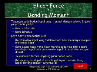
Internal Force Diagrams in Beams Normal Force, Shear Force and Moment Diagrams
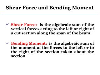
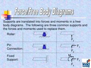
Area Method for Drawing Internal Force Diagrams (A Graphical Method) Positive Sign Conventions Positive external distributed load Positive internal shear force Positive internal moment N N Positive internal normal force
Area Method for Drawing Internal Force Diagrams (A Graphical Method) Let’s consider a general loading condition of a simply supported beam shown below: From a distance x from the left-end, consider a beam portion of length Δx
Area Method for Drawing Internal Force Diagrams (A Graphical Method) • On the left, the free body diagram of the beam segment of length delta-x is shown: • By considering that the segment is in equilibrium, the following equations can be written: + (1) + (2) By dividing the both side of eq.’s (1) and (2) by Δx, taking the limit as Δx goes to zero, the following two very important eq.’s can be obtained. (3) (4)
Area Method for Drawing Internal Force Diagrams (A Graphical Method) Distributed for positive upward! • These two equations can be used in drawing shear and moment diagrams. E Interpretation!!! Interpretation!
Area Method for Drawing Internal Force Diagrams (A Graphical Method) (3) Equations (3) and (4) can also be written as follows: (4) If we integrate both sides of these equations, we can get the followings: Area under the Distributed force Change in shear force Change in Moment diagram Area under the shear force diagram
Area Method for Drawing Internal Force Diagrams (A Graphical Method) nth degree (n+1)th degree Due to these integral relations: If w(x) is an nth degree function then V(x) (n+1)th degree M(x) (n+2)th degree functions. ΔM (n+2)th degree M
Area Method for Drawing Internal Force Diagrams (A Graphical Method) • How would the external concentrated force and moments would affect the internal force diagrams: Concentrated external force Concentrated external moment If F is downward, shear force diagram would jump downward (in negative directions). In the reverse case, the diagram would jump upward (positive direction). Clockwise external moment Mo would make the moment diagram jump in positive direction (upward), in the reverse case, the diagram would change in negative direction (downward).
Area Method for Drawing Internal Force Diagrams (A Graphical Method) Example 1: Draw the shear force and moment diagrams of the fixed beam shown below: Let’s first start by finding the reaction forces
Example 1 (cont.’ed): Expressions for the area method are given below: ve Since there is no distributed force, the slope of the shear force diagram is zero. eğim = 0
Example 2: For the simply supported beam shown below, draw the shear and moment diagrams. First, the support reactions: By applying equation of equilibrium:
Example 2 (cont.’ed): By using the expressions obtained for the area method:
Example 3: Draw the shear and moment diagrams for the fixed beam shown below.
Diagrams V(x) = 4- 2x Tek bir kesit incelenerek, diyagramlara ait denklemler de bulunabilirdi. Dikkat edilirse azalan eğimle, momentin değeri pozitif doğrultuda artıyor!
Example 4: Draw the shear and moment diagrams for the fixed beam shown below.
Example 5: Draw the shear and moment diagrams for the over-hanging beam shown below.
![Shear Force and Bending Moment Diagrams [SFD & BMD]](https://cdn1.slideserve.com/2511906/shear-force-and-bending-moment-diagrams-sfd-bmd-dt.jpg)


![Shear Force and Bending Moment Diagrams [SFD & BMD]](https://cdn3.slideserve.com/6594612/shear-force-and-bending-moment-diagrams-sfd-bmd-dt.jpg)

![Shear Force and Bending Moment Diagrams [SFD & BMD]](https://cdn5.slideserve.com/9656216/shear-force-and-bending-moment-diagrams-sfd-bmd-dt.jpg)