Download
1 / 82
2.63k likes | 6.6k Views
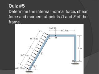
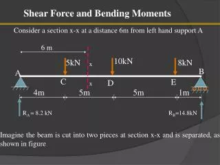
Shear Force and Bending Moment Diagrams [SFD & BMD]. 6 m. x. x. R A = 8.2 kN. R B =14.8kN. Shear Force and Bending Moments . Consider a section x-x at a distance 6m from left hand support A . 10kN. 5kN. 8kN. B. A. C. E. D. 4m. 5m. 5m. 1m.

E N D
6 m x x RA = 8.2 kN RB=14.8kN Shear Force and Bending Moments Consider a section x-x at a distance 6m from left hand support A 10kN 5kN 8kN B A C E D 4m 5m 5m 1m Imagine the beam is cut into two pieces at section x-x and is separated, as shown in figure
4 m 5 m 1 m 6 m 8.2 kN 9 m 14.8 kN 5kN A 10kN 8kN B To find the forces experienced by the section, consider any one portion of the beam. Taking left hand portion Transverse force experienced = 8.2 – 5 = 3.2 kN (upward) Moment experienced = 8.2 × 6 – 5 × 2 = 39.2 kN-m (clockwise) If we consider the right hand portion, we get Transverse force experienced = 14.8 – 10 – 8 =-3.2 kN = 3.2 kN (downward) Moment experienced = - 14.8 × 9 +8 × 8 + 10 × 3 = -39.2 kN-m = 39.2 kN-m (anticlockwise)
3.2 kN 39.2 kN-m 8.2 kN 14.8 kN 39.2 kN-m 3.2 kN 5kN A 10kN 8kN B Thus the section x-x considered is subjected to forces 3.2 kN and moment 39.2 kN-m as shown in figure. The force is trying to shear off the section and hence is called shear force. The moment bends the section and hence, called bending moment.
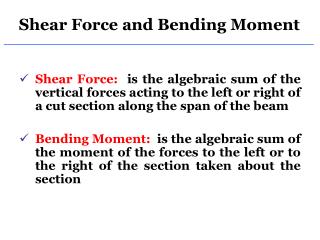
Bending moment (BM) at section: The algebraic sum of the moments of all forces acting on the beam either to the left or right of the section is known as the bending moment at a section 3.2 kN 3.2 kN F F Shear force at a section: The algebraic sum of the vertical forces acting on the beam either to the left or right of the section is known as the shear force at a section. 39.2 kN-m M Shear force at x-x Bending moment at x-x
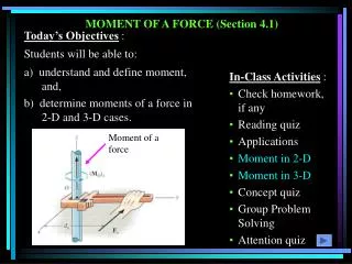
Moment and Bending moment Moment: It is the product of force and perpendicular distance between line of action of the force and the point about which moment is required to be calculated. Bending Moment (BM): The moment which causes the bending effect on the beam is calledBending Moment. It is generally denoted by ‘M’ or ‘BM’.
F F + ve shear force - ve shear force F F Sign Convention for shear force
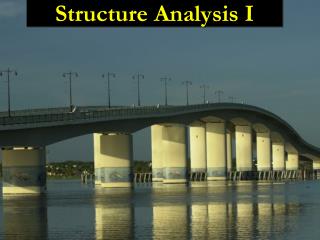
The bending moment is considered as Sagging Bending Moment if it tends to bend the beam to a curvature having convexity at the bottom as shown in the Fig. given below. Sagging Bending Moment is considered as positive bending moment. Sign convention for bending moments: Convexity Fig.Sagging bending moment[Positive bending moment]
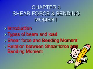
Similarly the bending moment is considered as hogging bending moment if it tends to bend the beam to a curvature having convexity at the top as shown in the Fig. given below. Hogging Bending Moment is considered as Negative Bending Moment. Sign convention for bending moments: Convexity Fig.Hogging bending moment [Negative bending moment ]
Shear Force Diagram (SFD): The diagram which shows the variation of shear force along the length of the beam is called Shear Force Diagram (SFD). Bending Moment Diagram (BMD): The diagram which shows the variation of bending moment along the length of the beam is called Bending Moment Diagram (BMD). Shear Force and Bending Moment Diagrams(SFD & BMD)
Point of Contra flexure [Inflection point]: It is the point on the bending moment diagram where bending moment changes the sign from positive to negative or vice versa. It is also called ‘Inflection point’. At the point of inflection point or contra flexure the bending moment is zero.
w kN/m x x1 x x1 L dx Relationship between load, shear force and bending moment Fig. A simply supported beam subjected to general type loading The above Fig. shows a simply supported beam subjected to a general type of loading. Consider a differential element of length ‘dx’ between any two sections x-x and x1-x1 as shown.
w kN/m x x1 V+dV M+dM M v O x x1 dx Fig. FBD of Differential element of the beam • Taking moments about the point ‘O’ [Bottom-Right corner of the differential element ] • M + (M+dM) – V.dx – w.dx.dx/2 = 0 • V.dx = dM Neglecting the small quantity of higher order It is the relation between shear force and BM
w kN/m x x1 V+dV M+dM M v O x x1 dx Fig. FBD of Differential element of the beam Considering the Equilibrium Equation ΣFy = 0 - V + (V+dV) – w dx = 0 dv = w.dx It is the relation Between intensity of Load and shear force
Variation of Shear force and bending moments Variation of Shear force and bending moments for various standard loads are as shown in the following Table Table: Variation of Shear force and bending moments
Sections for Shear Force and Bending Moment Calculations: Shear force and bending moments are to be calculated at various sections of the beam to draw shear force and bending moment diagrams. These sections are generally considered on the beam where the magnitude of shear force and bending moments are changing abruptly. Therefore these sections for the calculation of shear forces include sections on either side of point load, uniformly distributed load or uniformly varying load where the magnitude of shear force changes abruptly. The sections for the calculation of bending moment include position of point loads, either side of uniformly distributed load, uniformly varying load and couple Note: While calculating the shear force and bending moment, only the portion of the udl which is on the left hand side of the section should be converted into point load. But while calculating the reaction we convert entire udl to point load
10N 5N 8N B A C D 2m 2m 1m 3m E Example Problem 1 • Draw shear force and bending moment diagrams [SFD and BMD] for a simply supported beam subjected to three point loads as shown in the Fig. given below.
10N 5N 8N B A C D 2m 2m 1m 3m E RA RB Solution: Using the condition: ΣMA = 0 - RB × 8 + 8 × 7 + 10 × 4 + 5 × 2 = 0 RB = 13.25 N Using the condition: ΣFy = 0 RA + 13.25 = 5 + 10 + 8 RA = 9.75 N [Clockwise moment is Positive]
10N 5N 8N 2m 2m 1m 3m Shear Force Calculation: 0 1 9 8 3 2 4 6 7 5 9 8 0 2 3 1 1 4 5 7 6 RA = 9.75 N RB=13.25N Shear Force at the section 1-1 is denoted as V1-1 Shear Force at the section 2-2 is denoted as V2-2 and so on... V0-0 = 0; V1-1 = + 9.75 N V6-6 = - 5.25 N V2-2 = + 9.75 N V7-7 = 5.25 – 8 = -13.25 N V3-3 = + 9.75 – 5 = 4.75 N V8-8 = -13.25 V4-4 = + 4.75 N V9-9 = -13.25 +13.25 = 0 V5-5 = +4.75 – 10 = - 5.25 N (Check)
10N 5N 8N B A C E D 2m 2m 1m 3m 9.75N 9.75N 4.75N 4.75N 5.25N SFD 5.25N 13.25N 13.25N
10N 5N 8N B A C E D 2m 2m 1m 3m 9.75N 9.75N 4.75N 4.75N 5.25N SFD 5.25N 13.25N 13.25N
Bending Moment Calculation Bending moment at A is denoted as MA Bending moment at B is denoted as MB and so on… MA = 0 [ since it is simply supported] MC = 9.75 × 2= 19.5 Nm MD = 9.75 × 4 – 5 × 2 = 29 Nm ME = 9.75 × 7 – 5 × 5 – 10 × 3 = 13.25 Nm MB = 9.75 × 8 – 5 × 6 – 10 × 4 – 8 × 1 = 0 or MB = 0 [ since it is simply supported]
10N 5N 8N A B E C D 2m 2m 1m 3m 29Nm 19.5Nm 13.25Nm BMD
10N 5N 8N B A C D 2m 2m 1m 9.75N 9.75N 3m 4.75N 4.75N 5.25N 5.25N 29Nm SFD E 19.5Nm 13.25Nm 13.25N 13.25N BMD VM-34 Example Problem 1
10N 5N 8N B A C D 2m 2m 1m 9.75N 9.75N 3m 4.75N 4.75N 5.25N 5.25N 29Nm SFD E 19.5Nm 13.25Nm 13.25N 13.25N BMD
10kN 5kN 2kN/m B C A D E 3m 2m 3m 2m Example Problem 2 2. Draw SFD and BMD for the double side overhanging beam subjected to loading as shown below. Locate points of contraflexure if any. 5kN
10kN 5kN 5kN 2kN/m B C A D E 3m 2m 3m 2m RA RB Solution: Calculation of Reactions: Due to symmetry of the beam, loading and boundary conditions, reactions at both supports are equal. .`. RA = RB = ½(5+10+5+2 × 6) = 16 kN
10kN 5kN 5kN 2kN/m 4 5 2 3 6 7 1 8 9 0 8 9 2 3 4 5 7 1 6 0 2m 3m 2m 3m RA=16kN RB = 16kN Shear Force Calculation:V0-0 = 0 V1-1 = - 5kN V6-6 = - 5 – 6 = - 11kN V2-2 = - 5kN V7-7 = - 11 + 16 = 5kN V3-3 = - 5 + 16 = 11 kN V8-8 = 5 kN V4-4 = 11 – 2 × 3 = +5 kN V9-9 = 5 – 5 = 0 (Check) V5-5 = 5 – 10 = - 5kN
10kN 5kN 5kN 2kN/m B C A D E 11kN 3m 2m 3m 2m 5kN 5kN 5kN + + 5kN 5kN SFD 11kN 5kN
10kN 5kN 5kN 2kN/m B C A D E 3m 2m 3m 2m RB = 16kN RA=16kN Bending Moment Calculation: MC = ME = 0 [Because Bending moment at free end is zero] MA = MB = - 5 × 2 = - 10 kNm MD = - 5 × 5 + 16 × 3 – 2 × 3 × 1.5 = +14 kNm
10kN 5kN 5kN 2kN/m B C A D E 3m 2m 3m 2m 14kNm BMD 10kNm 10kNm
10kN 5kN 5kN 2kN/m B C A D E 14kNm 11kN 3m 2m 3m 2m 5kN 5kN 5kN + + 5kN 5kN BMD SFD 10kNm 11kN 10kNm
10kN 5kN 5kN 2kN/m B C A D E 3m 2m 3m 2m x x x x 10kNm 10kNm Points of contra flexure Let x be the distance of point of contra flexure from support A Taking moments at the section x-x (Considering left portion) x = 1 or 10 .`. x = 1 m
Example Problem Example Problem 3 3. Draw SFD and BMD for the single side overhanging beam subjected to loading as shown below. Determine the absolute maximum bending moment and shear forces and mark them on SFD and BMD. Also locate points of contra flexure if any. 5kN 2 kN 10kN/m A D C B 4m 1m 2m
5kN 2 kN 10kN/m A B RA RB 4m 1m 2m Solution : Calculation of Reactions: ΣMA = 0 - RB× 5 + 10 × 4 × 2 + 2 × 4 + 5 × 7 = 0 RB = 24.6 kN ΣFy = 0 RA + 24.6 – 10 x 4 – 2 + 5 = 0 RA = 22.4 kN
5kN 2 kN 10kN/m 5 2 4 3 7 0 1 6 5 4 0 2 3 7 6 1 4m RA=22.4kN 1m 2m RB=24.6kN Shear Force Calculations: V0-0 =0; V1-1 = 22.4 kN V5-5 = - 19.6 + 24.6 = 5 kN V2-2 = 22.4 – 10 × 4 = -17.6kN V6-6 = 5 kN V3-3 = - 17.6 – 2 = - 19.6 kN V7-7 = 5 – 5 = 0 (Check) V4-4 = - 19.6 kN
x = 2.24m 5kN 2 kN 10kN/m A C B D 4m RA=22.4kN 1m 2m RB=24.6kN 22.4kN 5 kN 5 kN 17.6kN 19.6kN 19.6kN SFD
5kN 2 kN 10kN/m X A D C B x X RA=22.4kN 4m 1m 2m RB=24.6kN Max. bending moment will occur at the section where the shear force is zero. The SFD shows that the section having zero shear force is available in the portion AC. Let that section be X-X, considered at a distance x from support A as shown above. The shear force at that section can be calculated as Vx-x = 22.4 - 10. x = 0 x = 2.24 m
5kN 2 kN 10kN/m A D C B RA=22.4kN 4m 1m 2m RB=24.6kN Calculations of Bending Moments: MA = MD = 0 MC = 22.4 × 4 – 10 × 4 × 2 = 9.6 kNm MB = 22.4 × 5 – 10 × 4 × 3 – 2 × 1 = - 10kNm (Considering Left portion of the section) Alternatively MB = -5 × 2 = -10 kNm (Considering Right portion of the section) Absolute Maximum Bending Moment is at X- X , Mmax = 22.4 × 2.24 – 10 × (2.24)2 / 2 = 25.1 kNm
5kN 2 kN 10kN/m X A D C B x = 2.24m X RA=22.4kN 4m 1m 2m RB=24.6kN Mmax = 25.1 kNm 9.6kNm Point of contra flexure BMD 10kNm
5kN 2 kN 10kN/m X A D C B x = 2.24m X RA=22.4kN 4m 1m 2m RB=24.6kN 22.4kN 9.6kNm 5 kN 5 kN Point of contra flexure x = 2.24m 17.6kN BMD 10kNm 19.6kN 19.6kN SFD
5kN 2 kN 10kN/m X A D C B x X RA=22.4kN 4m 1m 2m RB=24.6kN Calculations of Absolute Maximum Bending Moment: Max. bending moment will occur at the section where the shear force is zero. The SFD shows that the section having zero shear force is available in the portion AC. Let that section be X-X, considered at a distance x from support A as shown above. The shear force at that section can be calculated as Vx-x = 22.4 - 10. x = 0 x = 2.24 m Max. BM at X- X , Mmax = 22.4 × 2.24 – 10 × (2.24)2 / 2 = 25.1 kNm
5kN 2 kN 10kN/m X A D C B x = 2.24m X RA=22.4kN 4m 1m 2m RB=24.6kN Mmax = 25.1 kNm 9.6kNm Point of contra flexure BMD 10kNm
Let a be the distance of point of contra flexure from support B Taking moments at the section A-A (Considering left portion) A a = 0.51 m Mmax = 25.1 kNm 9.6kNm Point of contra flexure BMD 10kNm a A
Example Problem 4 • Draw SFD and BMD for the single side overhanging beam • subjected to loading as shown below. Mark salient points on • SFD and BMD. 60kN/m 20kN 20kN/m A B C D 3m 2m 2m
60kN/m 20kN 20kN/m A B C D RA 3m 2m 2m RB • Solution: Calculation of reactions: • ΣMA = 0 • RB× 5 + ½ × 3 × 60 × (2/3) × 3 +20 × 4 × 5 + 20 × 7 = 0 RB =144kN • ΣFy = 0 • RA + 144 – ½ × 3 × 60 – 20 × 4 -20 = 0 RA = 46kN
60kN/m 20kN 20kN/m 4 1 3 5 2 0 6 3 4 6 1 2 5 0 RB = 144kN RA = 46kN RA 3m 2m 2m RA Shear Force Calculations: V0-0 =0 ; V1-1 = + 46 kN V4-4 = - 84 + 144 = + 60kN V2-2 = +46 – ½ × 3 × 60 = - 44 kN V5-5 = +60 – 20 × 2 = + 20 kN V3-3 = - 44 – 20 × 2 = - 84 kN V6-6= 20 – 20 = 0 (Check)
60kN Parabola 46kN 20kN 44kN SFD 84kN Example Problem 4 60kN/m 20kN 20kN/m 4 1 2 3 5 6 3 4 6 1 2 5 RB = 144kN RA = 46kN RA 3m 2m 2m RA
60kN/m X 20kN 20kN/m A C x B D RB=144kN X RA =46kN 2m 2m 3m Max. bending moment will occur at the section where the shear force is zero. The SFD shows that the section having zero shear force is available in the portion AC. Let that section be X-X, considered at a distance ‘x’ from support A as shown above. The shear force expression at that section should be equated to zero. i.e., Vx-x = 46 – ½ .x. (60/3)x = 0 x = 2.145 m
60kN/m 20kN 20kN/m A C B D RB=144kN RA =46kN 2m 2m 3m Calculation of bending moments: MA = MD = 0 MC = 46 × 3 – ½ × 3 × 60 × (1/3 × 3) = 48 kNm[Considering LHS of section] MB = -20 × 2 – 20 × 2 × 1 = - 80 kNm [Considering RHS of section] Absolute Maximum Bending Moment, Mmax = 46 × 2.145 – ½ × 2.145 ×(2.145 × 60/3) × (1/3 × 2.145) = 65.74 kNm