Download

1 / 20
200 likes | 540 Views
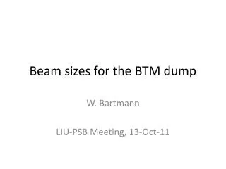
Present Status and Future Plans for the MKD Beam Dump Kickers. Acknowledgements: input gratefully received from Fritz Caspers, Enrique Gaxiola, Tom Kroyer, Viliam Senaj & Jan Uythoven. M.J. BARNES, AB/BT. LHC. LHC. SPS. SPS. 4 x MKI. PS Complex. PS Complex. PS. PS. 3 x MKDH.

E N D
Present Status and Future Plans for the MKD Beam Dump Kickers Acknowledgements: input gratefully received from Fritz Caspers, Enrique Gaxiola, Tom Kroyer, Viliam Senaj & Jan Uythoven. M.J. BARNES, AB/BT July 11, 2008
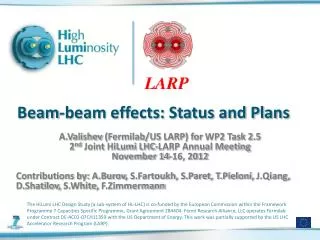
LHC LHC SPS SPS 4 x MKI PS Complex PS Complex PS PS 3 x MKDH 3 x MKDH 2 x MKDV 2 x MKDV 4 x MKI 4 x MKI CERN SPS & LHC Kicker Magnet Systems July 11, 2008
II. MKD Beam Dump System • When the beam can not be extracted: dumping of the beam using the MKD beam dump system (MD, emergencies...) • The system consists of: • Horizontal (MKDH) and vertical (MKDV) kicker magnets • Beam-dumps TIDV (E > 105 GeV/c) and TIDH (E < 37 GeV/c) • Function of the kicker magnets: • Sweep the beam to distribute the beam energy over a large volume of the absorbed block. • Function of the beam dumps: • Absorb the beam. July 11, 2008
II. Principle of Beam Dumping July 11, 2008
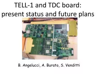
Beam MKDV2 MKDH1 MKDH2 MKDH3 MKDV1 PT100 sensor Ferrite MKDV magnet in lab MKDV magnet in lab MKD Kicker Magnets • The MKD Beam Dumping System kicker magnets are installed in SPS LSS1; • Two MKDV magnets & three MKDH magnets provide vertical & horizontal deflection, respectively; • ~30 year old equipment; • No transition pieces between vacuum tank and kicker magnet. Simplified schematic of MKD magnet layout in LSS1 July 11, 2008
MKD Magnet Parameters July 11, 2008
MKDV • MKDV1 & MKDV2 are 5 cell, transmission line, magnets constructed from (8C11) ferrite: • Each cell ~50cm long; • Above about 120C, 8C11 ferrites loose their magnetic properties. • Three parallel PFN’s (3 Ω each) feed two, electrically parallel, magnets (2 Ω each) – this implies a failure in one magnet has an impact upon field in another; • Thyratron and ignitron switches are used for MKDV: • Thyratrons provide fast rise-time capability & the ignitrons conduct a significant duration of the high current; • Three PFNs were necessary for current sharing between switches; • Limited dynamic range of ~4.3 (~11 kV to ~46 kV on PFN) – for PS2 it will be necessary to dump at 50 GeV/c (or maybe even 26 GeV/c – TBD). Hence a dynamic range of 9 (or maybe 18) will be required. • Temperature probes not fitted to magnets installed in LSS1 (PT100’s fitted to magnet in lab); • No measures taken to reduce beam coupling impedance to ferrite; • No transition pieces, between magnet tank and magnet frame, installed in LSS1. July 11, 2008
MKDH • MKDH1, MKDH2 & MKDH3 are lumped inductance magnets constructed from 0.35mm thick (or thinner), C-shaped, steel plates: • Thickness of the plate is parallel to the beam direction. • No problems with Curie temperature. Temperature limit will be due to mechanical constraints (150C ??). • In the early 2000’s, ignitron switches were replaced with Fast High Current Thyristors (FHCT’s): • The FHCT’s permit magnet current to be proportional to the beam energy over a dynamic range of 30 (from injection at 15 GeV/c to a top energy of 450 GeV/c); • Each magnet has its own capacitor bank (precharge of 10 kV produces a magnet current of 21 kA amplitude); • Temperature probes not fitted to magnets installed in LSS1; • No measures taken to reduce beam coupling impedance to steel; • No transition pieces, between magnet tank and magnet frame, installed in LSS1. July 11, 2008
Beam Induced Heating • Kicker magnets are heated by the beam due to their beam coupling impedance. Heating is caused by coupling between beam and real part of impedance. • High intensity beam can result in high power deposition. July 11, 2008
Aperture Longitudinal Impedance: Analytical Calculation (1) From CERN-SL-2000-04 AP, by H. Tsutsui, pp7-10: Longitudinal impedance per unit length Above equation is for 2D (infinite length) geometry. Analysis appears to allow for complex permeability and permittivity. July 11, 2008
Ferrite vap X hap Ferrite Aperture Longitudinal impedance per unit length Longitudinal Impedance: Analytical Calculation (2) Coding equation 27 (slide 10) in Mathematica format: Longitudinal impedance depends upon frequency, horizontal aperture, vertical aperture, relative permittivity and relative permeability. July 11, 2008
Longitudinal Impedance: Analytical Calculation (3) Applying equations from slide 11: c.f. ~2.6kΩ meas. MKE-S: 3.4kΩ MKE-L: 3.2kΩ • Notes: • Equations on slides 10 & 11 are for ferrite and hence not really applicable to a laminated steel MKDH magnet …. • smooth nature of curves. MKDH1,2: 1.6kΩ MKDV2: 150Ω c.f. ~200Ω meas. July 11, 2008
Longitudinal Measurements (Note: impedance data in following plot is scaled according to length of tank rather than magnet length; therefore actual impedance per metre is larger than shown in plot) • Apertures (hap x vap): • MKE-L: 147.7 x 35mm; • MKE-S: 135 x 32mm; • MKI: 54 x 54mm; • MKDV2: 56 x 83mm. Cell Length: • MKE: ~24cm; • MKDV2: ~50cm. From presentation to SPSU Study Team meeting on May 13, 2008: • MKE: serigraphy (painted stripes) reduces power deposition, in ferrite, by a factor of: • >4 for LHC beam; • ~7 for CNGS beam. • MKI: 15 screen conductors reduce power deposition, in ferrite, by a factor of ~40 for LHC beam. MKE: no stripes MKE (S6): stripes on 2 of 7 cells MKE (L10): stripes on all cells MKI: no screen MKDV2: no beam screen or transition pieces. Spikes due to cell length ??? MKI: 15 screen conductors July 11, 2008
CNGS Beam: Power Depositions • Calculated power deposition based on: • CNGS beam spectra measurements made by G. Arduini and T. Bohl (4.5 s period) – see Note-2004-39; • 2.5x10¹³ protons per pulse; • A total cycle duration of 6 s. • Use measured Real Impedance Longitudinal Data, for MKDV2 (see slide 13), without “spikes” (200 MHz intervals used): • “2 x” 7 W/m • Use analytical calculation for Real Impedance Longitudinal Data, for MKDH1,2 (see slide 12), (200 MHz intervals used): • “2 x” 32 W/m • Note: for MKE-L10, using measured Real Impedance Longitudinal Data, (see slide 13), scaled by 2.2/1.7: • “2 x” 25 W/m Thottest-equilibrium=35C (based on 26C tunnel) July 11, 2008
Printed strips in MKE-L10 Interdigital comb structure 20mm spacing surface discharge MKE: Beam Coupling Impedance Reduction • Beam coupling impedance is reduced using conductive stripes (serigraphy), i.e. interleaved comb structure, directly printed onto the ferrite blocks and a reliable contact to the metallic HV plates at either side; • Capacitive coupling between stripes (stripes carry beam image current). July 11, 2008
MKI: Beam Coupling Impedance Reduction Z Metallization – to give coupling capacitance Note: 0.7 x 2.7 mm conductors implemented for HV reasons. July 11, 2008
MKE: no shielding Transverse Impedance Measurements • Information re Transverse Impedance, and measurement techniques, can be found in: Tom Kroyer’s presentation “Wire Measurements on the MKE Extraction Kicker Magnets” APC meeting 10/11/2006. H V V MKE: stripes on all cells H H V Shielding increases transverse impedance at ~100MHz, but gives some reduction in transverse impedance above ~300MHz. July 11, 2008
Summary • MKDV2 longitudinal impedance, unshielded, is generally lower than that of MKE-L10 with full serigraphy (slide 13). • “Spikes” on measured longitudinal impedance (slide 13), which are not present in analytical calculation (slide 12), are probably attributable to magnet cell length. • Shielding increases MKE magnets transverse impedance at ~100 MHz, but reduces transverse impedance above ~300 MHz (slide 17). • No beam impedance measurements carried out on MKDH magnets: effect of laminated steel (permeability, permittivity, conductivity, plate thickness), versus ferrite, therefore not quantified. July 11, 2008
Future Plans • Remove third PFN from MKDV installation, i.e. two PFN’s of 2 Ω each, each with an individual magnet (2 Ω each) [reliability issue]; • For PS2 operation a dynamic range of 9 (or maybe 18) is required: development of a (fast) semiconductor switch for MKDV may be required; • What will be the available beam gap for field rise-time for the MKDV’s ? • Measure longitudinal and transverse impedance of MKDV magnet with transition pieces installed – measured impedance may be higher than without transition pieces, because of “bypass effect” without transition pieces; • Measure longitudinal and transverse impedance of MKDH magnet (effect of laminated steel ….); • Is beam shielding necessary for MKDV magnets since MKDV2 longitudinal impedance, unshielded, is generally lower than that of MKE-L10 with full serigraphy? • Beam shielding necessary for MKDH magnets? • Are transition pieces between magnet and tank necessary? July 11, 2008
Bibliography • T. Bohl, “CNGS Beam in the SPS: Beam Spectra”, Note-2004-39 • F. Caspers “Impedance Measurement of the SPS MKE Kicker by means of the Coaxial Wire Method”, PS/RF/Note 2000-004 • F. Caspers, “A Retrofit Technique for Kicker Beam-Coupling Impedance Reduction”, CERN-AB-2004-048 • E. Gaxiola et al, “Experience with Kicker Beam Coupling Reduction Techniques”, PAC2005 E. Gaxiola, “SPS Extraction Kicker Performance with Impedance Reduction Measures”, http://ab-div.web.cern.ch/ab-div/Meetings/APC/2006/apc061110/EG-APC-10-11-2006.pdf • P.E. Faugeras et al., “A Laminated-Iron Fast-Pulsed Magnet”, CERN-SPS/ABT/77-16. • T. Kroyer, “Wire Measurements on the MKE Extraction Kicker Magnets”, http://ab-div.web.cern.ch/ab-div/Meetings/APC/2006/apc061110/TK-APC-10-11-2006.pdf • T. Kroyer et al, “Longitudinal and Transverse Wire Measurements for the Evaluation of Impedance Reduction Measures on the MKE Extraction Kickers”, AB-Note-2007-028 • H. Tsutsui, “Some Simplified Models of Ferrite Kicker Magnet for Calculation of Longitudinal Coupling Impedance”, CERN-SL-2000-004 AP, http://doc.cern.ch/archive/electronic/cern/preprints/sl/sl-2000-004.pdf • J. Uythoven, “MKE Heating and Measured Power Spectra: CNGS BEAMS” , http://ab-div.web.cern.ch/ab-div/Meetings/APC/2004/apc041210/uythoven.pdf • J. Uythoven et al, “Beam Induced Heating of the SPS Fast Pulsed Magnets”, EPAC2004 July 11, 2008