Download
1 / 16
160 likes | 186 Views
Explore the challenges and proposed solutions for optimizing Linac RF modulators. Discover maintenance needs, tube replacements, power supply upgrades, and future-proofing strategies.

E N D
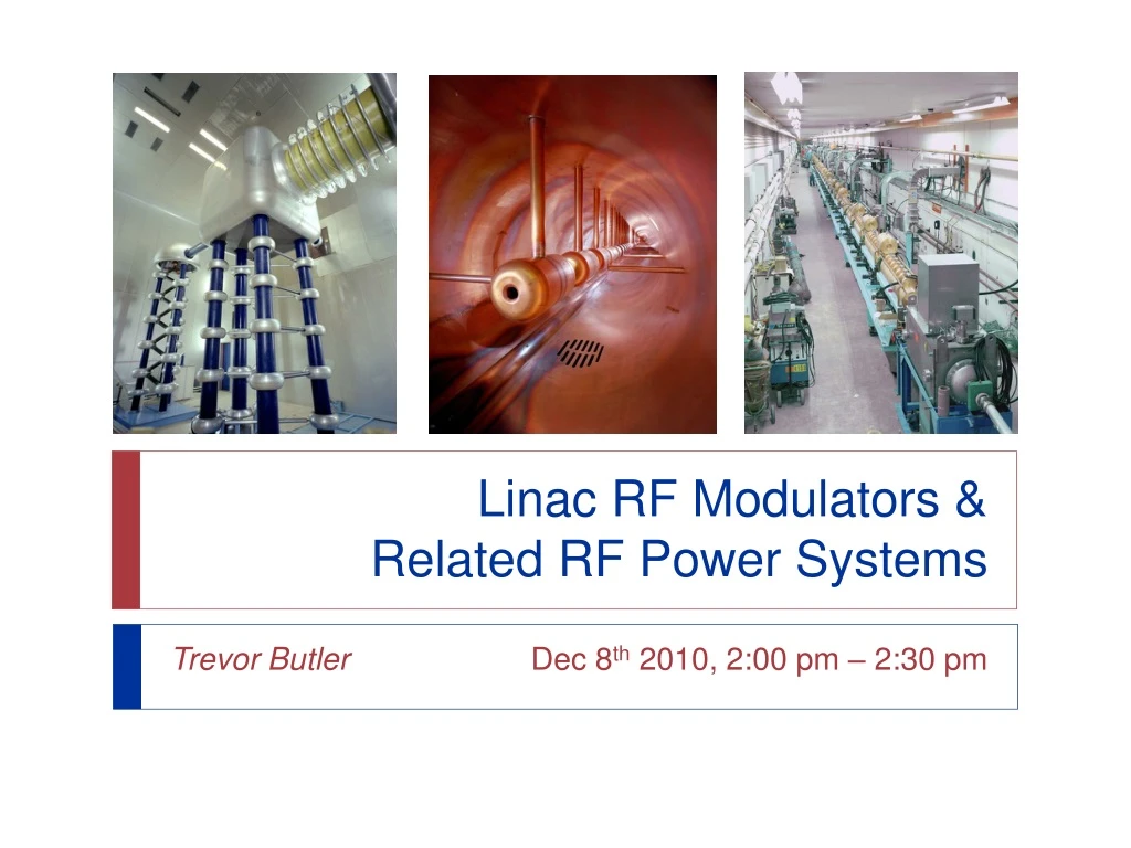
Linac RF Modulators &Related RF Power Systems Trevor Butler Dec 8th 2010, 2:00 pm – 2:30 pm
LE Linac RF Power Amplifier Chain 5 LE (201.25 MHz) Linac RF Stations (0.75–116.5 MeV) First 200 MeV Beam – Nov 30th 1970 • LLRF System 2 mW • Pre-Amplifier 4W • IPA1 – Solid State Amplifier 400 W • IPA1 – Burle 7651 Tetrode 4 kW • Driver – Burle 4616 Tetrode 175 kW • PA – Burle 7835 Triode 4 MW Trevor Butler
LE Linac Modulators Overview • Modulators use vacuum switch tubes to provide pulsed voltage to the anode of the Burle 7835 power amplifier. • Original design contracted by Continental Electronic (Dallas TX) in the late 60’s. • Minor upgrade in the early 80’s to replace 2 vacuum tube (Y631) video driver to solid state (2SK183V) FET video driver. • The main series regulator tube, (F1123) was discontinued 10 years ago. • Other accelerator RF systems use direct feedback driving the RF input to the main power amplifier (PA) to regulate the cavity field. • Since in our application, the 7835 is run grounded grid (cathode driven), it is unstable with low or no RF drive and the anode/plate voltage is modulated instead of the RF driver amplitude to regulate the cavity accelerating field. • The modulator requires linear operation of the “switch” tubes to set the accelerating field anywhere from 0.5 to 4 MW. • The LLRF system, upgraded a few years ago, uses a feed-forward loop to drive the modulator with an additional “boost” pulse to compensate for beam loading. Trevor Butler
LE Linac Modulators Block Diagram Trevor Butler
LE Linac Modulators Present Situation • Modulators are a major source of downtime in the Linac • 57 % of downtime over the past 10 years • DC Power supplies – Built directly to the frame and need to be repaired in place, which leads to long downtimes. A modular power supply system would be more efficient in diagnosing and repairing the modulator • Switch Tubes – The main power “switch” tubes in the modulator are no longer manufactured and are a major cause of modulator downtime • Fiber-optic TX / RX – Equipment is also discontinued should be upgraded to a modern instrumentation-grade analog data link system. • Relays & Interlocks – Most relays are not long manufactured. Few spares • FET keyer module – The first stage amplifier after the fiber-optic data link is discontinued, although an amply supply is currently on hand. • Diagnostics – Lack of reliable diagnostics equipment. Troubleshooting the modulator is very difficult since the equipment runs at high voltage and most measurements need to be observed when at full voltage and full loading • Personnel – All of the “original” Linac personnel have since retired, which has left an large experience deficient (100+ man years) in repairing the linac modulator & RF systems. This will likely lead to an increase in Linac downtime in the future. Trevor Butler
LE Linac Modulator Specifications Modulator Voltage: 50 kV maximum Modulator Current: 350 Amps F1123 Switch Tubes (>100 Amps each w/ 50kV Standoff!!!) • Voltage Pulse into Power Tube • Without Beam 20 – 30 kV flat top • With Beam 35 kV peak (40 kV Maximum) • Load: 80 to 140 Ohm (100 Ohm Typical Load) • Frequency Response: DC to 1 MHz • Pulse Width: 300 us – 500 us • 350 us typical (100 us rise/fall &150 us flat-top) • Pulse Repetition Rate: 15 Hz • Pulse Duty Cycle: 0.75 % maximum • Output Pulse Control: • 5 kV–35 kV (120 Ohms) / 5 kV–30 kV (80 Ohms) • Linearity: < +/- 20 % without external feedback over output pulse control range • Gain: 10,000 minimum • Slewing Rate: 20 kV/us minimum • Turn-On Rise/Fall Time:150 us typical • Total Delay: < 300 ns Trevor Butler
LE Modulator Electrical Schematic • CPI F1123 • “Switch” Tubes • operated as • linear amplifiers • 50 kV Standoff • ~100 Amps each • ~350 Amps Total • CPI-Eimac • ML-6544 • Power Triode • Maximum (20 kV, 75 Amp, 1 kW ) • 2.8 kV Typical • Uses 2 per modulator and 1 per driver screen modulator (5+1 Stations) • 18 tubes total • High Production Tube for CPI • Used in multiple radar and science applications • Not expected to be discontinued anytime soon • Manufactured by Westinghouse, ITT, Richardson, Varian, CPI, now nobody • Use 3 per station (5+1) = 18 total • Series-pass regulator between the capacitor bank and Burle 7835 Power Triode anode • No replacement part available • Rebuilt by Kennetron & Econco • Econco* – Can’t Rebuild Grids • *Problem – Bad grids are a typical type of failure in these tubes. Therefore, they need two tubes (one as a donor) to rebuild a tube with a bad grid Trevor Butler
LE Modulator Proposed Solutions • Replacement of the various power supplies in the Modulator • 6544 Anode (8kV, 375mA), F1123 Bias (3kV, 400mA), 6544 Bias On (3kV, 400mA), etc. (~$200k) • Are a significant proportion of the downtime and would improve reliability and stability • Replacement of just the F1123 switch tubes • Continental Electronics Inc. is also currently looking at the possibility of finding a manufacturer who will make/design switch tubes or find a tube that will replace the F1123 as the primary tube in our modulators (2) • Replacement of the Entire Modulator Floating Deck • Most elegant and complete solution • Would require minimal downtime to install each unit (~1 week) • Interfacing with present electronics would be simplified since there is only power in and modulator ready interlock out • Continental Electronics Inc. designed the original modulator and has developed a design idea for a new tube modulator using a CPI 8973 Triode (1) • A new modulator based on Marx Generator technology and combining switched cells with linear cells and including a bouncer circuit. (2) • Evaluate a proposed modulator design made by DTI Corporation to a specification similar to our own. This is also early in the review cycle and so have no estimate on time or cost.(2) (1) Status of the Low-Energy Linac 200-MHz RF Stations (C.W. Schmidt, R. Webber, E. McCrory, L. Allen, A. Moretti, M. Popovic, L. Wahl, K. Quinn, J. Walters, R. Pasquinelli, J. Reid) FERMILAB-TM-2166 March 2002 (2) Proton Source Task Force Report (William Pellico) 2010 Trevor Butler
LE Linac Switch Tube Deck Trevor Butler
LE Linac 7835 Filament PS • Ongoing Upgrade project, slated to be installed during the next shutdown • Old System has many drawbacks • Poorly calibrated filament current readbacks • Interlock system with unavailable parts and bad layout • Operator interface with no connection to controls system • Does not compensate for changes in line voltage since the inductrol does not move during normal operation • Main problem • Line voltage suffers from day and night fluctuations • As line voltage changes, 7835 filament current changes • For maximum lifetime, the 7835 filament current should be left low as possible • Therefore, overhead is placed on the filament current set point to insure the 7835 PA enough power to run at full power day and night • This overhead reduces the overall life of the tube! New Motor Worn Gears 7835 Filament Inductrol (Voltage Regulator) Trevor Butler
LE Linac 7835 Filament PS Upgrade • Compensates for day/night line voltage changes • Calibrated current read backs • New PLC based interlock & controls • New Inductrol Drive Motor • Future touch panel operator interface • Intergraded into ACNET control system • Increase lifetime of the 7835 tubes LRF4 – upgraded w/ new controls & motor New PLC based control system Trevor Butler
LE Linac Related RF Power Systems • LE Linac Gradient Regulator & Interlock System • Minor upgrades since originally built • Need to consider replacement as part of any future modulator upgrade • Cavity Tuner Controls and Electronics • Implement logic internally in the new LLRF • Build new module to power the stepping motor • Instrumentation and Controls Power Supplies • Need upgrading to modern supplies • Many are original and have failed due to “dried up” caps • LE Linac 7835 Filament Inductrol • Extensive gear wear on some stations • Need to test and acquire GE Inductrol Voltage Regulator with gear set Trevor Butler
LE Linac Modulators Summary • In order to run the modulator for the next 15 years, there needs to be an ample supply of parts for the modulator. This includes power supplies, passive components, relays, and most importantly, vacuum tubes. • The three main power tubes in the modulator, the F1123 switch tubes are no longer manufactured and depending on the tube rebuilders to continue to rework the tubes we have in-house is not an ideal long-term plan • The task of redesigning the modulator without using vacuum tubes is very difficult. • The simplest option would be to replace the entire deck with a new type of tube and all associated electronics (power supplies, interlocks, etc.) • There are many other systems in the Linac that are showing significant signs of wear and many parts are no longer manufactured that need to be part of a long term plan to insure both the modulator and other systems continue to run well into the future. Trevor Butler
BACKUP SLIDESLE Linac ModulatorsDetailed Block Diagram Trevor Butler
BACKUP SLIDESLE Linac Modulator Waveforms LRF3 – No Beam LRF3 – With Beam Trevor Butler


