Download
1 / 10
110 likes | 345 Views
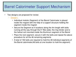
Barrel Calorimeter Support Mechanism. Two designs are proposed for review Design1. Individual module (Segment) of the Barrel Calorimeter is placed inside the magnet with the help of a support structure holding the segment inside the magnet

E N D
Barrel Calorimeter Support Mechanism • Two designs are proposed for review • Design1. • Individual module (Segment) of the Barrel Calorimeter is placed inside the magnet with the help of a support structure holding the segment inside the magnet • Secure the Segment at 4 locations along the 4m length with bolts running all the way through the 6” filler plate, the ring-Girder and to the helical coil mounted inside the Aluminum segment of the Barrel • Place the next segment, secure it with the bolts and repeat the above procedure for all the 46 remaining segments • A total of 192 bolts are required to hold the 48 individual segments of the Barrel calorimeter(48 bolts at one location to hold the segment)
Barrel Calorimeter Assembly Procedure Coil 1 Step1. Coil 1 inserts into the Iron yoke1 Ring-Girder Step2. 6 inch Iron plate and the Ring girder is bolted to the yoke Step3. Similarly all the other 4 Iron-yokes, coils and Ring-Girders are positioned in place Click for the next slide Iron-Yoke1
Coil 1 Barrel Calorimeter Assembly Procedure Step1. Coil 1 inserts into the Iron yoke1 Step2. 6 inch Iron plate with the Ring girder is bolted to the yoke Step3. Similarly all the other 3 Iron-yokes, coils and Ring-Girders are positioned in place 6 Inch Plate Rollers Ring-Girder Iron-Yoke1
Coil 6 Inch Plate Barrel Calorimeter Iron Yoke Ring Girder Rollers
Heli-coil insert in the aluminum plate Cut To accommodate the vacuum port 48 Threaded Rods holding the 48 Barrel Calorimeter modules
-Design 2 • This design involves assembling the barrel Calorimeter outside the magnet • Individual modules of the barrel calorimeter are assembled inside the 2cm thk carbon-fiber cylinder supported by a structure • The upper modules are bolted to the carbon-fiber cylinder • The cylinder is rolled into the magnet on rollers fixed to the ring-girder • 10 tones Hilman-rollers are located at three points on the circumference of the ring-girder • This option of assembling the barrel calorimeter provides us ample amount of time to assemble the barrel in par with the hall construction • Reduces the labor involved in fixing the 192 threaded rods into the barrel and extending it to the out-side of the filler plate • 10 threaded rods are installed to hold the cylinder and the Barrel Calorimeter in place once it has been assembled in the magnet
Carbon-Fiber Cyc HELI-COIL INSERT SUPPORT STRUCTURE HOLDING THE CARBON-FIBER CYC SETUP FOR ASSEMBLING THE BCAL OUTSIDE THE MAGNET
R65cm R92.5 3 Rollers Bolted to the Ring-girder