Download
1 / 18
180 likes | 301 Views
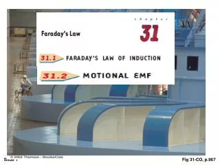
This chapter explores the concept of electromagnetic induction, demonstrating that an electromotive force (emf) can be induced in a circuit by changing magnetic fields, a principle discovered by Michael Faraday and Joseph Henry in 1831. By analyzing various experiments, such as moving magnets near loops of wire and connecting circuits, we illustrate the fundamental behaviors of induced currents. Faraday's law of induction, which states that induced emf is proportional to the rate of change of magnetic flux, is also discussed alongside practical applications in electric motors and generators.

E N D
Introduction The focus of our studies in electricity and magnetism so far has been the electric fields produced by stationary charges and the magnetic fields produced by moving charges. This chapter deals with electric fields produced by changing magnetic fields. Experiments conducted by Michael Faraday in England in 1831 and independently by Joseph Henry in the United States that same year showed that an emf can be induced in a circuit by a changing magnetic field. His many contributions to the study of electricity include the invention of the electric motor, electric generator, and transformer, as well as the discovery of electromagnetic induction and the laws of electrolysis.
To see how an emf can be induced by a changing magnetic field, let us consider a loop of wire connected to a galvanometer, as illustrated in Figure 31.1 • When a magnet is moved toward a loop of wire connected to a sensitive ammeter, the ammeter deflects as shown, indicating that a current is induced in the loop. • When the magnet is held stationary, there is no induced current in the loop, even when the magnet is inside the loop. • When the magnet is moved away from the loop, the ammeter deflects in the opposite direction, indicating that the induced current is opposite that shown in part (a). • Changing the direction of the magnet’s motion changes the direction of the current induced by that motion.
Faraday’s experiment. When the switch in the primary circuit is closed, the ammeter in the secondary circuit deflects momentarily. The emf induced in the secondary circuit is caused by the changing magnetic field through the secondary coil Faraday concluded that an electric current can be induced in a circuit (the secondary circuit in our setup) by a changing magnetic field.
The secondary circuit behaves as though a source of emf were connected to it for a short time. It is customary to say that an induced emf is produced in the secondary circuit by the changing magnetic field. The statement, known as Faraday’slaw of induction, can be written the emf induced in a circuit is directly proportional to the time rate of change of the magnetic flux through the circuit
If the circuit is a coil consisting of N loops all of the same area and if B is the flux through one loop, an emf is induced in every loop; thus, the total induced emf in the coil is given by the expression Suppose that a loop enclosing an area A lies in a uniform magnetic field B, as shown in Figure 31.3. the magnetic flux through the loop is equal to B = BA cos
2- A flat loop of wire consisting of a single turn of cross sectional area 8.00 cm2 is perpendicular to a magnetic field that increases uniformly in magnitude from 0.500 T to 2.50 T in 1.00 s. What is the resulting induced current if the loop has a resistance of 2.00 Ω?
5- The square loop is made of wires with total series resistance 10.0 . It is placed in a uniform 0.10 T magnetic field directed perpendicular into the plane of the paper. The loop, which is hinged at each corner, is pulled as shown until the separation between points A and B is 3.00 m. If this process takes 0.100 s, what is the average current generated in the loop? What is the direction of the current? مساحة المثلث = نصف حاصل ضرب ضلعين منه × جا الزاوية المحصورة بينهم
Some applications of Faraday`s law Fig 31-5, p.971
This section describe the emf induced in a conductor moving through a constant magnetic field The straight conductor of length l shown in Figure 31.8 is moving through a uniform magnetic field directed into the page. For simplicity, we assume that the conductor is moving in a direction perpendicular to the field with constant velocity v under the influence of some external agent The electrons in the conductor experience a force FB = q v x B that is directed along the length l , perpendicular to both v and B . Under the influence of this force, the electrons move to the lower end of the conductor and accumulate there, leaving a net positive charge at the upper end. As a result of this charge separation, an electric field is produced inside the conductor. The charges accumulate at both ends until the downward magnetic force qvB is balanced by the upward electric force qE.
The electric field produced in the conductor is related to the potential difference across the ends of the conductor according to the relationship). Thus, where the upper end is at a higher electric potential than the lower end. Thus, a potential difference is maintained between the ends of the conductor as long as the conductor continues to move through the uniform magnetic field. If the direction of the motion is reversed, the polarity of the potential difference also is reversed.
A conducting bar sliding with a velocity v along two conducting rails under the action of an applied force F app. The magnetic force FBopposes the motion, and a counterclockwise current I is induced in the loop - القدرة The conversion of mechanical energy first to electrical energy and finally to internal energy in the resistor. Fig 31-10a, p.974