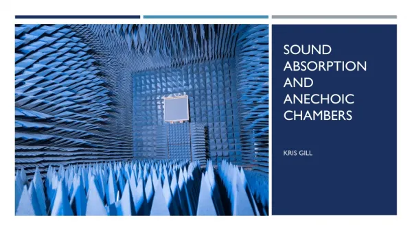
Anechoic Chamber
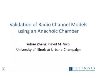
Anechoic Chamber. System Design Review 10/14/2011. Project Overview. Anechoic Chamber. Test antennas. Designed for 2-4 GHz To be used by future senior design teams Easy to use Robust . Three antennas designed and built One Wideband A ntenna One High Gain Antenna


Anechoic Chamber
E N D
Presentation Transcript
Anechoic Chamber System Design Review 10/14/2011
Project Overview Anechoic Chamber Test antennas • Designed for 2-4 GHz • To be used by future senior design teams • Easy to use • Robust • Three antennas designed and built • One Wideband Antenna • One High Gain Antenna • One ReducedSize Antenna
Project plan Phase I- Chamber Design Phase II- Absorber • Assembly • Isolation testing • Isolation improvements and final test • Design • Cutting/ scaling/ purchasing • Application • Quiet zone testing • Final review/design edits
Project Plan (cont.) Phase III – Rx antenna mount Phase IV – Control System • Design • Arm construction • Slider construction • Motor/Housing construction • Control system housing construction • Wiring and insolation • System Level Design • GUI • LabView control level • Microcontroller level • Interface
Project Plan (cont.) Phase V – Antennas Phase VI – Final review and testing • Design • Construction • Testing • Final tests • Calibration • Documentation of chamber properties • User’s manuel
Key Risks • Standard gain reading can not be taken • Calibration sequence does not accurately apply offset so readings are wrong • Chamber is too complicated for someone without RF background to use • Absorber is not placed correctly and allows for reflections
Control System Diagram • Linear flow • Micro Controller interfaces with LabView • Reset option for users to stop program mid-execution • When normal execution completes, exports all data to a text file to be used with programs such as Matlab