Download
1 / 8
80 likes | 227 Views
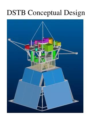
IRMS Rotator Module Support Structure Conceptual Design. B. Weber October 3, 2011. Support Structure Based on IRIS Design Concept. IRMS support weldment (green). IRIS supports (transparent). Mount brackets (red)

E N D
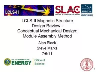
IRMS Rotator Module Support Structure Conceptual Design B. Weber October 3, 2011
Support Structure Based on IRIS Design Concept IRMS support weldment (green) IRIS supports (transparent) Mount brackets (red) bridge between the interface ring and the locations where Keck Observatory defining points are normally attached to the module (4X) IRMS rotator module interface Ring weldment (purple)
IRMS Support Structure W/Out IRIS Overlay IRIS to NFIRAOS Interface Overlay (transparent) Available instrument space envelope (transparent)
Conceptual Design Analysis Overview • IRMS Weight Estimate: 13,000 lbs. (5,909 kg.) • Instrument: 5,500 lbs. (2,500 kg.) • Rotator Module: 2,500 lbs. (1,136 kg.) • Support Structure: 5,000 lbs. (2,273 kg.) • Support Structure FEA Results Summary (FEA report at: http://www.oir.caltech.edu/twiki_oir/bin/view/TMT/IRMS/ObservatoryInterfaces) • Static vertical load Safety Factor = 5.6 (yield strength) • 1g lateral load minimum Safety Factor = 3.6 (yield strength) • 1st Natural frequency of support structure (only) = 53.3 Hz • The static vertical load translated through the hexapod legs creates a maximum lateral radial load in the NFIRAOS structure = ~10,600 lbs. (4,818 kg.) tension.