Download
1 / 28
570 likes | 1.64k Views
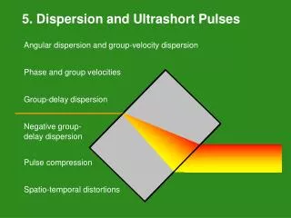
5. Dispersion and Ultrashort Pulses. Angular dispersion and group-velocity dispersion Phase and group velocities Group-delay dispersion Negative group- delay dispersion Pulse compression Spatio-temporal distortions. Dispersion in Optics.

E N D
5. Dispersion and Ultrashort Pulses • Angular dispersion and group-velocity dispersion • Phase and group velocities • Group-delay dispersion • Negative group- • delay dispersion • Pulse compression • Spatio-temporal distortions
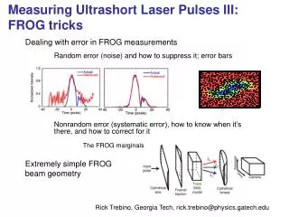
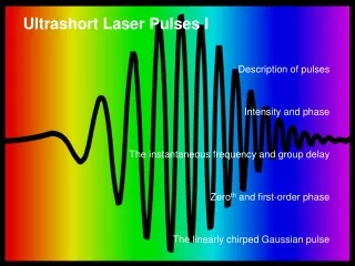
Dispersion in Optics The dependence of the refractive index on wavelength has two effects on a pulse, one in space and the other in time. Dispersion disperses a pulse in space (angle): “Angular dispersion” dn/dl Dispersion also disperses a pulse in time: “Chirp” d2n/dl2 Both of these effects play major roles in ultrafast optics.
Calculating the Group velocity vgºdw /dk Now, w is the same in or out of the medium, but k = k0 n, where k0 is the k-vector in vacuum, and n is what depends on the medium. So it's easier to think of w as the independent variable: Using k = wn(w) / c0, calculate: dk /dw = ( n + w dn/dw ) / c0 vg = c0 / ( n + wdn/dw) = (c0 /n) / (1 + w /n dn/dw) Finally: So the group velocity equals the phase velocity when dn/dw = 0, such as in vacuum. Otherwise, since n increases with w, dn/dw > 0, and: vg < vphase.
Calculating Group Velocity vs. Wavelength • We more often think of the refractive index in terms of wavelength, • so let's write the group velocity in terms of the vacuum wavelength l0.
The group velocity is less than the phase velocity in non-absorbing regions. • vg = c0 / (n + wdn/dw) • Except in regions of anomalous dispersion (which are absorbing), dn/dw is positive, that is, near a resonance. So vg < c for these frequencies!
H(w) Optical device or medium Spectral Phase, GDD, and Optical Devices Recall that the effect of a linear passive optical device (i.e., lenses, prisms, etc.) on a pulse is to multiply the frequency-domain field by a transfer function: where H(w)is the transfer function of the device/medium: for a medium Since we also write E(w) = √S(w) exp[-ij(w)], the spectral phase of the output light will be: We simply add spectral phases. Note that we CANNOT add the temporal phases!
Expanding the phase in a medium jH(w) = k(w) L To account for dispersion, expand the phase (k-vector) in a Taylor series: The first few terms are all related to important quantities. The third one is new: the variation in group velocity with frequency: is the “group velocity dispersion.”
The effect of group velocity dispersion • GVD means that the group velocity will be different for different wavelengths in the pulse. early times late times vgr(yellow) < vgr(red) Because ultrashort pulses have such large bandwidths, GVD is a bigger issue than for cw light.
Calculation of the GVD (in terms of wavelength) Recall that: and Okay, the GVD is: Units: s2/m or (s/m)/Hz or s/Hz/m Simplifying:
GVD in Optical Fibers Note that fiber folks define GVD as the negative of ours. Sophisticated cladding structures, i.e., index profiles have been designed and optimized to produce a waveguide dispersion that modifies the bulk material dispersion
GVD yields group delay dispersion (GDD). We can define delays in terms of the velocities and the medium length L. The phase delay: so: The group delay: so: GDD = GVD L The group delay dispersion (GDD): so: Units: fs2 or fs/Hz
Manipulating the phase of light Recall that we expand the spectral phase of the pulse in a Taylor Series: and we do the same for the spectral phase of the optical medium, H: phase delay group delay group delay dispersion (GDD) So, to manipulate light, we must add or subtract spectral-phase terms. For example, to eliminate the linear chirp (second-order spectral phase), we must design an optical device whose second-order spectral phase cancels that of the pulse: i.e.,
Propagation of the pulse manipulates it. • Dispersive pulse broadening is unavoidable. • If j2 is the pulse 2nd-order spectral phase on entering a medium, and k”L is the 2nd-order spectral phase of the medium, then the resulting pulse 2nd-order phase will be the sum: j2 + k”L. • A linearly chirped input pulse has 2nd-order phase: • Emerging from a medium, its 2nd-order phase will be: (This result pulls out the ½ in the Taylor Series.) This result, with the spectrum, can be inverse Fourier-transformed to yield the pulse. A positively chirped pulse will broaden further; a negatively chirped pulse will shorten. Too bad material GDD is always positive in the visible and near-IR…
So how can we generate negative GDD? This is a big issue because pulses spread further and further as they propagate through materials. We need a way of generating negative GDD to compensate.
Suppose that some optical element introduces angular dispersion. Angular dispersion yields negative GDD. If frequency w0 propagates a distance L to plane S’, j then frequency w sees a phase delay of j(w) Optical element w Input beam L P0 Computing the 2nd derivative of j(w), assuming a is small: w The GDD due to angular dispersion is always negative!
w w Lsep How can we use dispersion to introduce negative chirp conveniently? A prism pair has negative GDD Assume Brewster angle incidence and exit angles. Always positive (in visible and near-IR) Always negative! This term assumes that the beam grazes the tip of each prism This term allows the beam to pass through an additional length, Lpriam, of prism material. Vary the second term to tune the GDD!
Pulse Compressor This device has negative group-delay dispersion and hence can compensate for propagation through materials (i.e., for positive chirp). The longer wavelengths have a longer path. It’s routine to stretch and then compress ultrashort pulses by factors of >1000
Adjusting the GDD maintains alignment. Any prism in the compressor can be translated perpendicular to the beam path to add glass and reduce the magnitude of negative GDD. Remarkably, this does not misalign the beam. New prism position Original path through prism New beam path through prism Original and new path out of the prism Original prism position
Different prism materials The required separation between prisms in a pulse compressor can be large. The resulting negative GDD is proportional to the prism separation and the square of the dispersion. Compression of a 1-ps, 600-nm pulse with 10 nm of bandwidth (to about 50 fs). Kafka and Baer, Opt. Lett., 12, 401 (1987) It’s best to use highly dispersive glass, like SF10, or gratings.
Diffraction-grating pulse compressor The grating pulse compressor also has negative second-order phase. Grating #2 w w where d = grating spacing (same for both gratings) Lsep Note that, as in the prism pulse compressor, the larger Lsep, the larger the negative GDD. Grating #1
j'' j''' 2nd- and 3rd-order phase terms for prism and grating pulse compressors Grating compressors offer more compression than prism compressors. Piece of glass Note that the relative signs of the 2nd and 3rd-order terms are opposite for prism compressors and grating compressors.
Compensating 2nd and 3rd-order spectral phase Use both a prism and a grating compressor. Since they have 3rd-order terms with opposite signs, they can be used to achieve almost arbitrary amounts of both second- and third-order phase. Prism compressor Grating compressor Given the 2nd- and 3rd-order phases of the input pulse, jinput2 and jinput3, solve simultaneous equations: This design was used by Fork and Shank at Bell Labs in the mid 1980’s to achieve a 6-fs pulse, a record that stood for over a decade.
Pulse Compression Simulation Resulting intensity vs. time with only a grating compressor: Note the cubic spectral phase! Using prism and grating pulse compressors vs. only a grating compressor Resulting intensity vs. time with a grating compressor and a prism compressor: Brito Cruz, et al., Opt. Lett., 13, 123 (1988).
Pulse compressors achieve amazing results, but, if not aligned well, they can introduce spatio-temporal distortions, such as “spatial chirp.” • Propagation through a prism pair produces a beam with no angular dispersion, but the color varies spatially across the beam. • Care must be taken to cancel out this effect with the 3rd and 4th prisms. Prism pairs are inside nearly every ultrafast laser, so we’re just asking for spatial chirp. Color varies across beam
Spatial chirp is difficult to avoid. • Simply propagating through a tilted window causes spatial chirp! Different colors have different refractive indices and so have different refraction angles. Color varies across beam n(w) Because ultrashort pulses are so broadband, this distortion is very noticeable—and problematic!
Angular dispersion also causes pulse fronts to tilt. Phase fronts are perpendicular to the direction of propagation. Because group velocity is usually less than phase velocity, pulse fronts tilt when light traverses a prism. Pulse-front tilt and angular dispersion are manifestations of the same effect and their magnitudes are directly proportional to each other.
Angular dispersion causes pulse-front tilt even when group velocity is not involved. Diffraction gratings also yield a pulse-front tilt. The path is simply shorter for rays that impinge on the near side of the grating. Of course, there’s angular dispersion, too. Since gratings have about ten times the dispersion of prisms, they yield about ten times the tilt.