Chapter 13 Small-Signal Modeling and Linear Amplification
320 likes | 577 Views
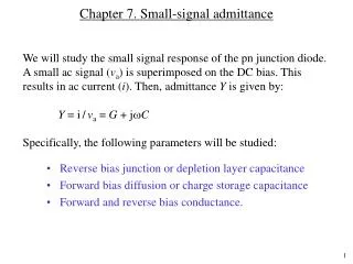
Chapter 13 Small-Signal Modeling and Linear Amplification. Chapter Goals. Understanding of concepts related to: Transistors as linear amplifiers dc and ac equivalent circuits Use of coupling and bypass capacitors to modify dc and ac equivalent circuits Small-signal voltages and currents

Chapter 13 Small-Signal Modeling and Linear Amplification
E N D
Presentation Transcript
Chapter Goals Understanding of concepts related to: • Transistors as linear amplifiers • dc and ac equivalent circuits • Use of coupling and bypass capacitors to modify dc and ac equivalent circuits • Small-signal voltages and currents • Small-signal models for diodes and transistors • Identification of common-emitter amplifiers • Amplifier characteristics such as voltage gain, input and output resistances and linear signal range • Rule-of-thumb estimates for voltage gain of common-emitter amplifiers.
Introduction to Amplifiers • The BJT is an an excellent amplifier when biased in the forward-active region. • The FET can be used as an amplifier if operated in the saturation region. • In these regions, the transistors can provide high voltage, current and power gains. • DC bias is provided to stabilize the operating point in the desired operation region. • The DC Q-point also determines • The small-signal parameters of the transistor • The voltage gain, input resistance, and output resistance • The maximum input and output signal amplitudes • The overall power consumption of the amplifier
A Simple BJT Amplifier The BJT is biased in the forward active region by dc voltage sources VBE and VCC = 10 V. The DC Q-point is set at, (VCE, IC) = (5 V, 1.5 mA) with IB = 15 mA. Total base-emitter voltage is: Collector-emitter voltage is: This produces a load line.
BJT Amplifier (continued) If changes in operating currents and voltages are small enough, then IC and VCE waveforms are undistorted replicas of the input signal. A small voltage change at the base causes a large voltage change at the collector. The voltage gain is given by: The minus sign indicates a 1800 phase shift between input and output signals. An 8 mV peak change in vBE gives a 5 mA change in iB and a 0.5 mA change in iC. The 0.5 mA change in iC gives a 1.65 V change in vCE .
A Simple MOSFET Amplifier The MOSFET is biased in the saturation region by dc voltage sources VGS and VDS = 10 V. The DC Q-point is set at (VDS, IDS) = (4.8 V, 1.56 mA) with VGS = 3.5 V. Total gate-source voltage is: A 1 V p-p change in vGS gives a 1.25 mA p-p change in iDS and a 4 V p-p change in vDS. Notice the characteristic non-linear I/O relationship compared to the BJT.
A Practical BJT Amplifier using Coupling and Bypass Capacitors In a practical amplifier design, C1 and C3 are large coupling capacitors or dc blocking capacitors, their reactance (XC = |ZC| = 1/wC) at signal frequency is negligible. They are effective open circuits for the circuit when DC bias is considered. C2 is a bypass capacitor. It provides a low impedance path for ac current from emitter to ground. It effectively removes RE (required for good Q-point stability) from the circuit when ac signals are considered. • AC coupling through capacitors is used to inject an ac input signal and extract the ac output signal without disturbing the DC Q-point • Capacitors provide negligible impedance at frequencies of interest and provide open circuits at dc.
DC and AC Analysis -- Application of Superposition • DC analysis: • Find the DC equivalent circuit by replacing all capacitors by open circuits and inductors (if any) by short circuits. • Find the DC Q-point from the equivalent circuit by using the appropriate large-signal transistor model. • AC analysis: • Find the AC equivalent circuit by replacing all capacitors by short circuits, inductors (if any) by open circuits, dc voltage sources by ground connections and dc current sources by open circuits. • Replace the transistor by its small-signal model (to be developed). • Use this equivalent circuit to analyze the AC characteristics of the amplifier. • Combine the results of dc and ac analysis (superposition) to yield the total voltages and currents in the circuit.
DC Equivalent for the BJT Amplifier • All capacitors in the original amplifier circuit are replaced by open circuits, disconnecting vI, RI, and R3 from the circuit and leaving RE intact. The the transistor Q will be replaced by its DC model. DC Equivalent Circuit
AC Equivalent for the BJT Amplifier • The coupling and bypass capacitors are replaced by short circuits. The DC voltage supplies are replaced with short circuits, which in this case connect to ground.
AC Equivalent for the BJT Amplifier (continued) • By combining parallel resistors into equivalent RBand R, the equivalent AC circuit above is constructed. Here, the transistor will be replaced by its equivalent small-signal AC model (to be developed).
Hybrid-Pi Small-signal AC Model for the BJT Transconductance: • The hybrid-pi small-signal model is the intrinsic low-frequency representation of the BJT. • The small-signal parameters are controlled by the Q-point and are independent of the geometry of the BJT. Input resistance: Output resistance:
Small-signal Current Gain and Amplification Factor of the BJT The amplification factor is given by: For VCE << VA, mF represents the maximum voltage gain an individual BJT can provide, independent of the operating point. bo > bF for iC < IM, and bo < bF for iC > IM, however, bo and bF are usually assumed to be about equal.
Example bo Calculation for 2N2222A Choose the Q-point at about (5 V, 5 mA) for this analysis. Notice the slope of the DC current gain characteristic in this region. Ideally, the slope would be zero.
From Figure 3 for the 2N2222A BJT at the chosen Q-point… at about IC = 5 mA and 25 °C for bF = 180 Given the tolerances usually encountered in forward current gain, the assumption of bF = bo seems reasonable for preliminary analysis and initial designs.
Equivalent Forms of the Small-signal Model for the BJT • The voltage-controlled current source gmvbe can be transformed into a current-controlled current source, • The basic relationship ic=bib is useful in both dc and ac analysis when the BJT is biased in the forward-active region.
Small Signal Operation of BJT For linearity, ic should be directly proportional to vbe. for If we limit vbe to 5 mV, the relative change in ic compared to ICthat corresponds to small-signal operation is:
Small-Signal Analysis of the Complete C-E Amplifier: AC Equivalent • The AC equivalent circuit is constructed by assuming that all capacitances have zero impedance at signal frequency and the AC voltage source is at ground. • Assume that the DC Q-point has already been calculated.
Small-Signal Analysis of Complete C-E Amplifier: Small-Signal Equivalent Overall voltage gain from source vi to output voltage vo across R3is:
Capacitor Selection for the CE Amplifier The key objective in design is to make the capacitive reactance much smaller at the operating frequency f than the associated resistance that must be coupled or bypassed.
C-E Amplifier Input Resistance • The input resistance, the total resistance looking into the amplifier at coupling capacitor C1, represents the total resistance presented to the AC source.
C-E Amplifier Output Resistance • The output resistance is the total equivalent resistance looking into the output of the amplifier at coupling capacitor C3. The input source is set to 0 and a test source is applied at the output. But vbe=0. since ro is usually >> RC.
CE Amplifier Design Example Using LabVIEW Virtual Instruments
Amplifier Power Dissipation • Static power dissipation in amplifiers is determined from their DC equivalent circuits. Total power dissipated in C-B and E-B junctions is: where Total power supplied is: The difference is the power dissipated by the bias resistors.