Download
1 / 21
210 likes | 224 Views
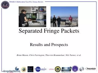
This text discusses the transportation of a muon beam through a beam line to a storage ring, specifically focusing on the alignment of the ring and beam line, trajectory displacement, and compensating for fringe fields. It also explores the use of a larger aperture inflector and the propagation of Twiss parameters through iron and other components.

E N D
Injection through iron and fringe field D. Rubin January 15, 2014 D. Rubin
Transport through M5 beam line to storage ring • Align ring/beam-line so that • Muon trajectory is centered in inflector (narrowest aperture), nominally tangent to storage ring and displaced 68mm + 9=77mm radially outward at inflector exit. Where x_i = 9mm (inflector half aperture) • What about a new inflector with a larger aperture (x_n)? Then the trajectory at the end of M5 line should be displaced D = x_n - x_i further outward. (D ~ 2 cm) • Meanwhile, fringe fields steer beam near upstream end of inflector, thus requiring some compensating angle (with respect to tangent line) at end of M5 line. • (To determine the initial angle and offset that will place the trajectory at the center of a new larger aperture inflector, requires a more expansive field map.) • Fringe field focusing • Vertical field increases from 0 to 1.5T along trajectory through gap => horizontal defocus – with equivalent 1 m long quadrupole with k ~ 0.35 m-2 • Difficult to compensate D. Rubin
B D. Rubin
Larger aperture inflector Existing inflector D. Rubin
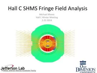
Gradient due to fringe from main dipole dBy / dr = 1.45T / 40cm = 3.625 T/m => k = 0.35 m-2 Path length through the fringe L ~ 1. Equivalent to the strongest quadrupole in the M5 line B D. Rubin
bx= 8.0 m by = 20.0 m h = 4m { At inflector exit For best match into ring K(Q27) = 0.774 m-2 D. Rubin
Questions? How can we place the ring with respect to the M5 line, to accommodate the existing as well as a larger aperture inflector? Do the final focus quadrupoles have sufficient aperture to clear a muon beam where both b and h are large? Do the final focus quadrupoles have sufficient gradient? (Is if possible to place Q27 even closer to the iron?) D. Rubin
How do twiss parameters propagate through iron, cryostat, inflector into ring D. Rubin
What are the fields along the route of injected beam ? From P. Debevec2012 D. Rubin
Width of backleg =544mm Width of gap = 1394-544 = 850 mm Distance from edge of iron to ideal orbit = 280mm Width of pole = 2 x 280mm From center of gap to backleg iron = 850-280=570mm Radius of central orbit = 7.112 m Field starts to fall off linearly 18cm from center of pole This is 570-180mm =390mm Then the gradient G = Bmax/.39 = 1.4 T/.39m = 3.58 T/m Inflector is 1.7m long. Tan (theta) = 1.7/(7.112 + 0.077) Radius of upstream end of inflector = 7.189 - sqrt(7.189^2+1.7^2)=0.198 So the inflector goes from 77mm to 198+77mm =275mm from center of pole D. Rubin
Radial beam motion • Beam exits yoke • Beam through outer coil • Beam through Inflector • Beam kicked onto orbit B D. Rubin
Inflector Geometry ~1.7 m m central orbit D. Rubin