Download
1 / 21
210 likes | 231 Views
WP2 progress on safety. E. Baussan. EUROnu CB Meeting Monday 10th & Tuesday 11th June 2011 CERN, Geneva, Switzerland. WP2 Progress on safety. Outlines: Introduction SB layout facility simulation One horn simulation Next steps. Toward a safety WP2 roadmap. WP2 Progress on safety.

E N D
WP2 progress on safety E. Baussan EUROnu CB Meeting Monday 10th & Tuesday 11th June 2011 CERN, Geneva, Switzerland
WP2 Progress on safety Outlines: • Introduction • SB layout facility simulation • One horn simulation • Next steps EUROnu CB Meeting
Toward a safety WP2 roadmap EUROnu CB Meeting
WP2 Progress on safety • Safety : preparation phase • Radiological risks • Determine the radiological risks (external or internal contamination) for each part of the facility. • Investigate biological protections with respect to the prompt dose and residual dose • Environmental impact studies • Non-radiological risks • Electrical risks, cooling system, maintenance operation…. EUROnu CB Meeting
Superbeam Facility beam dump Design of the SB line : • Proton Driver line • Experimental Hall • MW Target Station • Decay Tunnel • Beam Dump • Hot Cell / Spare area • Service Gallery • Power supply • Cooling system • Air-Ventilation system • Waste Area (to be defined) shielding spare area target/horn station decay tunnel (25 m) hot cell horn power supply and electronics gallery beam EUROnu CB Meeting 5
Safety : MW Target Station • MW Target Station : • Focusing System • Crane System • Automated robot • Mechanical structure for the four horns • Dose Rate Monitoring System • Residual Dose Rate Plateform • OperationunderheliumAtmosphere • flushingwith air • filter to measure radioactive pollution (dust, tritium …) • Investigation of otherradionucleide transport (environmentalconstraint) • … EUROnu CB Meeting
Superbeam Facility V. Zeter EUROnu CB Meeting
Superbeam Facility Chemical composition of Material: Target => Titanium Horn => Anticorodal 110 alloy Al (95.5%), Si(1,3%), Mg(1,2%), Cr(0.2%), Mn(1%),Fe (0.5%), Zn(0.2%), Cu(0.1%) Decay Pipe => Steel P355NH Fe(96.8%), Mn(1.65%), Si(0.5%), Cr(0.3%), Ni(0.3%), C(0.2%) Tunnel => Concrete O(52.9%), Si(33.7%), Ca(4.4%), Al(3,49%), Na(1,6%), Fe(1.4%), K(1,3%), H(1%), Mn(0.2%), C(0.01%) Surrounding Environment => Molasse O(49%), Si(20%), Ca,(9.7%), Al(6.4%), C(5%), Fe(3.9%), Mg(3.2%), K(1%), Na(0.5%), Mn(0.1%) Four horn station layout EUROnu CB Meeting
Energy deposition in the SB Layout Geometrical Dimension ot the SB Layout: EUROnu CB Meeting
Energy deposition in the SB Layout Beam dump (front view) Energy confined in the SB facility Beam dump (profile view) EUROnu CB Meeting
Time Evolution of the Dose Equivalent Rate After one day After one month After half year After a 10 year EUROnu CB Meeting
Environmental impact Activation in molasse molasse @ CERN concrete concrete A 6m thichness concrete wall surrounding all the layout limit the production of radionucleides in the molasse. Especially, the production of 22 Na and tritium could represent a negative impact by contaminating the ground water. EUROnu CB Meeting
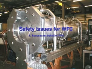
Safety Issues • Workingstrategy : • Normal intensityoperation : 4 hornsat 1.0 MW beam power • High intensityoperation : 3 hornsat 1.3 MW beam power • Optimisation of the horn design: • reduce maintenance operation on the four horn system: • Identify points reducing the lifetime of horns (mechanicalinstabilityduringbeamoperation, ) • Complex network of water pipes, difficulty to repair in case of leaks • Fastelectricalconnector • … • Hot Cellismandatory to repair/replace the target+horn system View of the horn View of the four horns EUROnu CB Meeting
Horn failure investigations B. Lepers EUROnu CB Meeting
Radiation simulations : Target Activation Evolution of the target activity with cooling time: Radionucleides after 1 day (Z,A) Radioactivity after 1 day (Bq.cm-3) EUROnu CB Meeting
Radiation simulations : Horn Activation Evolution of the horn activity with cooling time: Radionucleides after 1 day (Z,A) Radioactivity after 1 day (Bq.cm-3) EUROnu CB Meeting
Time evolution of the DER : Target+Horn After one day After one month After half year After a year EUROnu CB Meeting
Storage Area : Investigation Hot cell preliminary investigation: at 60cm distance from the outer conductor (calculation of the rates using 20cmx20cmx20cm mesh binning through out the layout -> choose a slice of x-axis with 20cm thickness and 60cm away Storage Area EUROnu CB Meeting
Storage Area : dose equivalent rate map 1month 1year > 1 Sv/h > 50 mSv/h 100years 50years > 0.01 mSv/h EUROnu CB Meeting
Next Steps : • Estimate the contribution of each element to the dose rate • Investigate the hot cell structure, maintenance operation • Individual and collective dose rate calculation with cooling times • Costing EUROnu CB Meeting