Download
1 / 19
190 likes | 203 Views
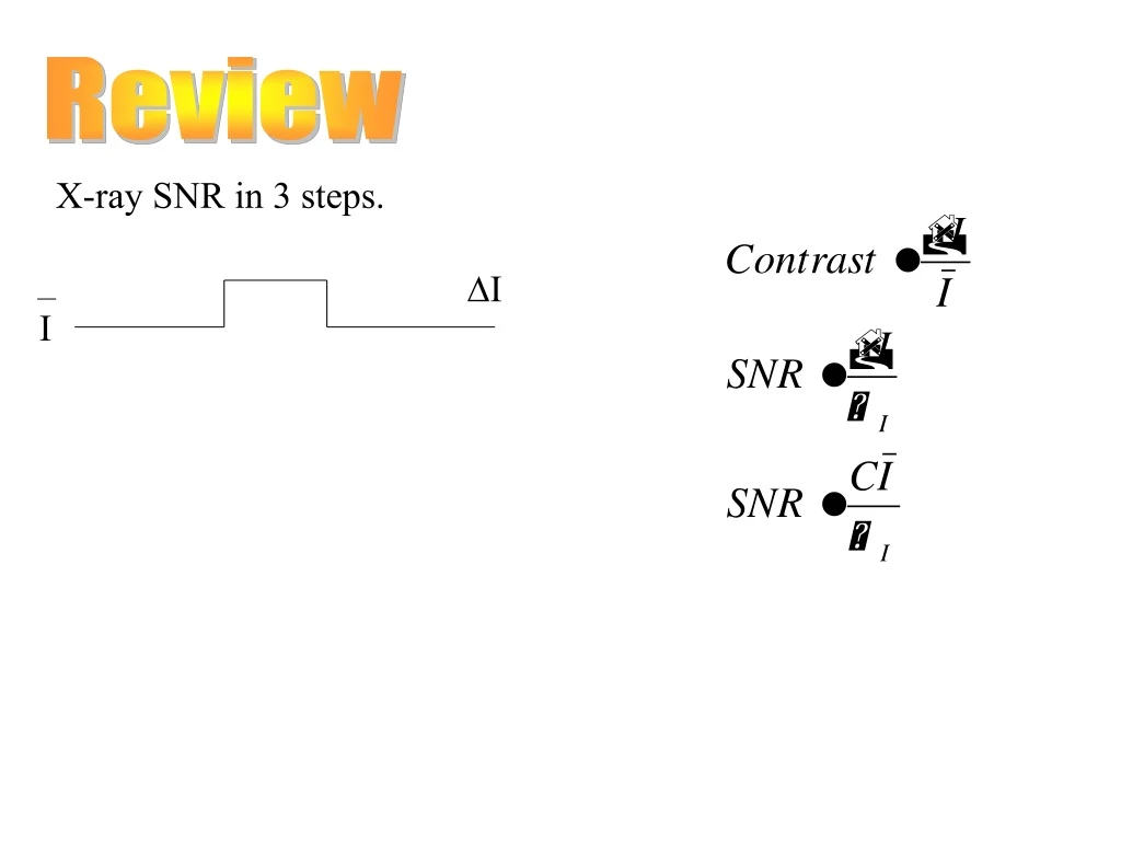
Review. X-ray SNR in 3 steps. ∆I. I. 1). X-ray transmission SNR Review Let N = average number of transmitted x-rays N = N 0 exp [ - ∫ dz ] Emission and transmission are Poisson processes. where = 2.5 x 10 10 photon 2 / cm 2 / Roentgen

E N D
Review X-ray SNR in 3 steps. ∆I I
1) X-ray transmission SNR Review Let N = average number of transmitted x-rays N = N0 exp [ - ∫ dz ] Emission and transmission are Poisson processes where = 2.5 x 10 10 photon2 / cm2 / Roentgen A = pixel area in cm2 ,h=screen efficiency R = dose t = transmission
2) Detection M X Z W Transmitted g1 g2 developed grains photons light grains / photons light photon /x-ray
Putting it all together… Let’s consider N again as the average number of transmitted, not captured, photons per unit area. g1 = hvx-ray / hvlight = light / x-ray = 5000 A0 / 0.2 A0 ≈ 25,000 Typically efficiency gives 500 to 1000 light photons per x-ray For worst case, g1 = 500 g2 = 1/200
Fluoroscopy • Image catheters • Image injections • Old Method Fluorescent screen Subject Source • is the solid angle subtended from a point on the detector to the pupil
Fluorescent screen Subject Source • is the solid angle subtended from a point on the detector to the pupil Fluoroscopy Instead of film, a fluorescent screen was first used. The problem is that the eye will only capture a portion of the light rays generated by the screen. How could the eye’s efficiency be increased?
Fluoroscopy • is the solid angle subtended from a point on the detector to the pupil Fluorescent screen Let’s calculate the equivalent of the screen efficiency in this system, the eye’s efficiency capturing light Where r = viewing distance ( minimum 20 cm) Te retina efficiency ( approx. .1) A = pupil area ≈ 0.5 cm2 8 mm pupil diameter(usually 2-3mm)
At best ≈ 10-5 Typically ≈ 10-7 Recall With g1 =103 light photons / x-ray g1g2 = 10310-5 = 10-2 at best Loss in SNR of 10 Have to up dose a factor of 100 ! (more likely to compromise resolution rather than dose) At each stage, we want to keep the gain product >> 1 or quantum effects will harm SNR.
Image Intensifier X-rays phosphor output screen g4 eye efficiency g3 phosphor g2 Electrostatic lenses Photo cathode Light photons converted into electrons with g2 Electrons accelerated and turned back into light photons with g3
Image Intensifier X-rays phosphor output screen g3 phosphor g2 g1 Electrostatic lenses Photo cathode
Image Intensifier X-rays phosphor g4 eye efficiency Anode g3 phosphor g2 g1 Photo cathode For each captured x-ray g1 =103 light photons g2 = electrons / light photons = 0.1 g1g2 = 100 g3 = emitted light photons / electron = 103 g4 = eye efficiency = 10-5 optimum g1g2g3g4 = 103 10-1 103 10-5 = 1 Section 5.2.6
Image Intensifier For each captured x-ray g1 =103 light photons g2 = electrons / light photons = 0.1 g1g2 = 100 g3 = emitted light photons / electron = 103 g4 = eye efficiency = 10-5 optimum g1g2g3g4 = 103 10-1 103 10-5 = 1 SNR loss =
Add a TV TV cathode g3 g2 g1 g4 Electronic focusing And amplification Lens efficiency 0 ≈ 0.04 Much better than eye. g1 = 103 g2 = 10 -1 g3 = 103 0 g4 = 0.1 electrons / light photon g1g2g3g4 = 4 x 10²
Additive TV Noise Up to now, if g1g2g3g4 >> 1 and all the intermediate gain products >> 1 But TV has an additive electrical noise component. Let’s say the noise power (variance) is Na2.
N Na = = kN In X-ray, the number of photons is modeled as our source of signal. We could consider modeling or expressing, Na ( which is actually a voltage), as its equivalent number of photons. Electrical noise then occupies some fraction of the signal’s dynamic range. Let’s use k to represent the portion of the dynamic range that is occupied by additive noise.
Typical TV For k2N >> 1 SNR ≈ C/k poor, not making use of radiation k2N << 1 k = 10-2 to 10-3 typically N = 105 photons / pixel Regular k = 10-2 k2N = 10 Better design k = 10-3 k2N = 10-1 Much Better!
}∆I Is + Ib Is Scatter 0 We will view scattered photons as increasing the background intensity. Scatter increases the level of the background and the lesion. Let the ratio of scattered photons to desired photons be Section 5.4.3
Scatter increases the level of the background and the lesion. }∆I Is + Ib Is Scatter 0 Conclusion: So does scatter affect contrast?
SNR Effects of Scatter Scatter doesn’t change the amount of signal. It is still DI. The variance of the background now depends on the variance of trans- mitted and scattered photons, however. Both are Poisson and independent so we can sum the variances. N2 = hN + hNs where Ns is mean number of scattered photons Here C is the scatter free contrast. So does SNR affect scatter? Grids to reduce scatter are described in Sec. 5.2.4