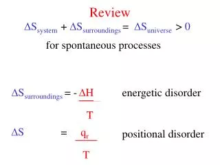
Review
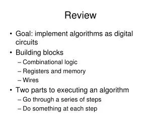
Review. Goal: implement algorithms as digital circuits Building blocks Combinational logic Registers and memory Wires Two parts to executing an algorithm Go through a series of steps Do something at each step. Going through a series of steps. Algorithm. Implementation. combinational

Review
E N D
Presentation Transcript
Review • Goal: implement algorithms as digital circuits • Building blocks • Combinational logic • Registers and memory • Wires • Two parts to executing an algorithm • Go through a series of steps • Do something at each step
Going through a series of steps Algorithm Implementation combinational logic State A state State register next_state State B State C State D
Having input affect the series of steps State A State B State C State D input == 0 input == 1
Doing something at each step • Datapath is composed of: • Combinational logic • Registers and memory • Wires • Control unit tells each datapath component what to do at each step by setting control signals
address_write clock memoryaddress register (MAR) address_in DPDT_SW[3:0] register 0 register 1 register 2 register 3 register 4 data_in data_out register 5 LED_RED[3:0] DPDT_SW[7:4] register 6 register 7 mem_write
control signals control signals
inputs control signals
always @* begin address_write = 1'b0; mem_write= 1'b0; next_state = state_reset; case (state) state_reset: begin next_state= state_decide; end state_decide: begin if (READ == 1'b1) begin next_state = state_read1; end else if (WRITE == 1'b1) begin next_state = state_write1; end else begin next_state = state_decide; end end
state_read1: begin address_write = 1'b1; next_state = state_decide; end state_write1: begin address_write = 1'b1; next_state = state_write2; end state_write2: begin mem_write = 1'b1; next_state = state_decide; end endcase end
parameter state_reset = 3’h0; parameter state_decide = 3’h1; parameter state_read1 = 3’h2; parameter state_write1 = 3’h3; parameter state_write2 = 3’h4; always @(posedge clock) begin if (reset == 1'b1) begin state <= state_reset; end else begin state <= next_state; end end
How to implement an algorithm as a digital circuit • Write the algorithm as a program • List datapath elements • Scalar variable implemented as register • Array variable implemented as memory • Arithmetic operation implemented as combinational logic • Rewrite the program to obey hardware limits • One operation at a time • Low-level sequencing • if statements can only execute “go to” • loops implemented as “if…go to”
How to implement an algorithm as a digital circuit • Connect datapath elements • One-bus style • Registers and memory get input from bus • Combinational logic gets input from registers • Outputs go to bus (via tri-state drivers)
How to implement an algorithm as a digital circuit • List control signals for each datapath element • Register: write • Memory: mem_write, address_write • Tri-state driver: drive
How to implement an algorithm as a digital circuit • Write control unit • Follow same steps as program • Most steps transfer data from one datapath element to another • If control unit needs to decide based on input, pass input value from register or combinational logic to control unit
i max element memory address data equal16 greater plus1 equal16_out greater_out
loop if (i==16) goto end read1 memory_address = i read2 element = mem[i] compare if (element > max) gotowrite_max, else goto increment write_max max = element increment i = i+1; goto loop end goto end
always @* begin element_write = 1'b0; element_drive = 1'b0; max_write = 1'b0; i_write = 1'b0; i_drive = 1'b0; plus1_drive = 1'b0; memory_write = 1'b0; memory_drive = 1'b0; address_write = 1'b0; next_state = state_reset; case (state) state_reset: begin next_state = state_loop; end state_loop: begin // if i is 16, then we're done if (equal16_out == 1'b1) begin next_state = state_end; end else begin next_state = state_read1; end end
state_read1: begin // transfer i to memory address i_drive = 1'b1; address_write = 1'b1; next_state = state_read2; end state_read2: begin // read memory[i] memory_drive = 1'b1; element_write = 1'b1; next_state = state_compare; end state_compare: begin // is memory[i] more than the current max? if (greater_out == 1'b1) begin next_state = state_write_max; end else begin next_state = state_increment; end end
state_write_max: begin // update max element_drive = 1'b1; max_write = 1'b1; next_state = state_increment; end state_increment: begin // increment i plus1_drive = 1'b1; i_write = 1'b1; next_state = state_loop; end state_end: begin next_state = state_end; end endcase end
top.v (partial) register u3 (clock, reset, element_write, bus, element_out); register u4 (clock, reset, max_write, bus, max_out); register u5 (clock, reset, i_write, bus, i_out); greater u6 (element_out, max_out, greater_out); equal16 u7 (i_out, equal16_out); plus1 u8 (i_out, plus1_out); ram u9 (bus, ~address_write, clock, bus, memory_write, memory_out); tristate u10 (element_out, bus, element_drive); tristate u11 (plus1_out, bus, plus1_drive); tristate u12 (i_out, bus, i_drive); tristate u13 (memory_out, bus, memory_drive); // display max on HEX2, HEX3 hexdigit u16 (max_out[3:0], HEX2); hexdigit u17 (max_out[7:4], HEX3); control u18 (clock, reset, greater_out, equal16_out, element_write, element_drive, max_write, i_write, i_drive, plus1_drive, memory_write, memory_drive, address_write);
greater.v module greater( input wire [7:0] in1, input wire [7:0] in2, output reg out); always @* begin if (in1 > in2) begin out = 1'b1; end else begin out = 1'b0; end end endmodule