Chapter 6 – External Memory
Chapter 6 – External Memory. Magnetic Disk. Group # 6 Ramon Canseco Jorge Mora I brahim Babun Dominic Tang How Bao Kun Ricardo Gonzalez . What is a Magnetic disk?.

Chapter 6 – External Memory
E N D
Presentation Transcript
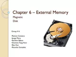
Chapter 6 – External Memory Magnetic Disk • Group # 6 • Ramon Canseco • Jorge Mora • Ibrahim Babun • Dominic Tang How • Bao Kun • Ricardo Gonzalez
What is a Magnetic disk? • Circular platter constructed of non-magnetic material, the material is called substrate, coated with a magnetizable material. • Recently the use of glass substrate have introduce the following benefits: • Improve uniformity of the magnetic film, to increase reliability. • Reduces read-write errors • Better stiffness to reduce disk Dynamics • Greater ability to withstand shock and damge.
Key points of magnetic disk • Remain the most important component of external memory. • Used in system raging from personal computer to super computer. • Both removable and fixed, or hard disk. • For greater performance and larger server system a RAID disk is used. Also later on, you will learn about optical storage.
Magnetic disk write mechanism • Data are recorded on and later retrieved from the disk via a conducting coil named the head. • In many system there are two heads: • A read head and a write head. • During the write mechanism the head is stationary while the patter rotates beneath it.
Write mechanism • Electricity flows through a coil that produces a magnetic filed. • Electric pulses are sent to the write head: • Resulting in the magnetic patterns recorded.
Data Organization and Formatting • Tracks are a concentric set of rings on the platter. • Tracks are separated by Gaps. Gaps prevent errors due to misaligned heads. • Sectors is how data is transferred to and from disk. • Constant Angular velocity is the disk at a fixed speed.
Advantage: Disadvantage: • The advantage of using CAV is that individual blocks of data can be directly addressed by track and sector. • The disadvantage of CAV is that the amount of data that can be stored on the long outer tracks is the only same as what can be stored on theshortinner tracks. Constant Angular Velocity
A removable disk can be removed and replaced with another disk. • A non-removable diskis permanently mounted in the disk drive; the hard disk in a personal computer is a non-removable disk. • Movable-head disk, there is only one read-write head. Physical Characteristics
Winchester Disk Format(Seagate ST506) • The ST-506 was the first 5.25 inch hard disk drive. • Introduced in 1980 by Seagate Technology • It stores up to 5 megabytes after formatting and cost $1500
The term Winchester was originally used by IBM as a code name for the 3340 disk model prior to its announcement. • The 3340 was a removable disk pack with the heads sealed within the pack. The term is now applied to any sealed-unit disk drive with aerodynamic head design. The Winchester disk is commonly found and built into personal computers and workstations, where it is referred to as a hard disk.
Disk Performance Parameters • T = b/rN • Where : • T transfer time • b number of bytes to be transferred • N number of bytes on a track • r rotation speed, in revolutions per second • Thus the total average access time can be expressed as Ta = Ts + 1 /(2r) + b/rN • Where Ts is the average seek time.
RAID(Redundant Array of Independent Disks ) RAID is a technology that provides increased storage functions and reliability through redundancy. - The RAID scheme consists of seven levels, zero through six. - The RAID strategy employs multiple disk drives
RAID 0 (also known as a stripe set or striped volume) • Following are the key points to remember for RAID level 0. - Minimum 2 disks. - Excellent performance ( as blocks are striped ). - No redundancy ( no mirror, no parity ). - Don’t use this for any critical system.
RAID 1 • Following are the key points to remember for RAID level 1. - Minimum 2 disks. - Good performance ( no striping. no parity ). - Excellent redundancy ( as blocks are mirrored ). the important aspect of this RAID is that information on one disk or partition is being replicated.
RAID 2(bit-level striping with dedicated Hamming-code parity) • RAID 2 requires fewer disks than RAID 1 • A RAID 2 stripes data at the bit (rather than block) • uses Hamming code for error correction • The use of Hamming code permits using 7 disks in RAID 2 • Because of its high cost and complexity, RAID 2 never really caught on
RAID 3 • byte-level striping with dedicated parity • only a single redundant disk • parallel access with small strips of data • Reconstruction of parity disks
Advantages Disadvantages • Very high read and write data transfer rate • Insignificance impact from disk failure • Efficient low ratio of parity disks to data • Transaction rate equals to single disk drive • Complex controller design RAID 3
RAID 4 • block-level striping with dedicated parity • independent access array • allows I/O requests to be performed • strips are relatively large • bit-by-bit parity strip is calculated
Advantages Disadvantages • Very high read data transaction rate • Efficient low ratio of parity disks to data • Quite complex controller design • Worst write transaction and write aggregate transfer rates • Difficult and inefficient data rebuild RAID 4
RAID 5 • block-level striping with distributed parity • distributes the parity strips across all disks • round-robin scheme • avoids the bottleneck found in RAID 4.
Advantages Disadvantages • Highest read data transaction rate • Good aggregate transfer rate • Efficient low ratio of parity disks to data • The most complex controller design • Difficult to rebuild during disk failure RAID 5
RAID 6 • block-level striping with double distributed parity • two different parity calculations • stored in separate blocks on different disks • extremely high data availability
Advantages Disadvantages • Extremely high data fault tolerance • Sustain multiple simultaneous drive failures • More complex controller design • Controller overhead is extremely high RAID 5
Optical Disk Products • CD • CD-ROM; CD-R; CD-RW; • DVD • DVD-R; DVD-RW • Blu-Ray
CD Operation Basic One-Side Disc Operation Double-Sided Disc Operation
CD-ROM Block Format SYNC: Identifies the beginning of a block. Header: Contains the block address and the mode byte. Mode 0: Specifies a blank data field Mode 1: Specifies the use of error-correction= 2048 bytes Mode 2: Specifies 2336 bytes of user data with no error correcting code. Auxiliary: Additional user data in mode 2. 288 bytes used as error-correcting code in Mode 1
High Definition Optical Disks • Blu Ray: • Same size as CDs and DVD (1.2mm) • Contains 25GB of data per layer • Available with Triple (100GB) and Quadruple • (128GB) Layers • The name Blu-ray refer to blue laser used to • read disc • HD DVD • No longer in production • Lost optical disc war to Blu Ray
Questions • For CDs and DVDs, what does, pits and lands ( no change in elevation) converts to in digital signals? • What was a major factor in the Blu Ray, HD DVD optical disk war?
Magnetic Tape • Sequential access • Serpentine recording • Very cheap • Backup and archive • Linear Tape-Open (LTO) Tape Drives • Developed late 1990s • Open source alternative to proprietary tape systems
Access to data • Move from record 1 to N. • Read records 1 through N-1 one at a time • If beyond N • Rewind tape x distance and begin reading • Tape Directory • Physical tape location for a given data block • Detected while winding tape
USB flash driver Universal Serial Bus—Flash—Driver
Name and Definition • As the name of this device, What USB flash driver is a driver which using flash memory chip as its storage media and communicating with computer or other device via Universal Serial Bus.
Universal Serial Bus • it is an industry standard developed in the mid-1990s that defines the cables, connectors and protocols used for connection, communication and power supply between computers and electronic devices.
Device classes • USB defines class codes used to identify a device’s functionality and to load a device driver based on that functionality. This enables every device driver writer to support devices from different manufacturers that comply with a given class code.Deviceclasses include:
USB 1.1 and before;USB 2.0 • USB 2.0: Released in April 2000.Added higher maximum bandwidth of 480 Mbit/s (60 MB/s) (now called "Hi-Speed"). Further modifications to the USB specification have been done via Engineering Change Notices (ECN). The most important of these ECNs are included into the USB 2.0 specification package available from USB.org • On-The-Go Supplement 1.3: Released in December 2006.USB On-The-Go makes it possible for two USB devices to communicate with each other without requiring a separate USB host. In practice, one of the USB devices acts as a host for the other device. • USB 1.0: Released in January 1996.Specified data rates of 1.5 Mbit/s (Low-Bandwidth) and 12 Mbit/s (Full-Bandwidth). Does not allow for extension cables or pass-through monitors (due to timing and power limitations). Few such devices actually made it to market. • USB 1.1: Released in September 1998.Fixed problems identified in 1.0, mostly relating to hubs. Earliest revision to be widely adopted.
USB 3.0 and future • There have been many reports of USB 3.0 equipment only transferring data at USB 2.0 speed, usually with a message "This USB Mass Storage Device can transfer information faster if you connect it to a Super-Speed USB 3.0 port". This has been due to several causes, including drivers, certain cables specified as USB 3.0 (problems disappeared when a different cable was used), order of starting equipment, equipment needing to be disconnected and reconnected, and overclocked computers
Flash • Flash memory (either NOR or NAND-type type) is invented by Dr. Gang Fujio from Toshiba Corporation in 1984. According to Toshiba Flash the name "Flash" is following colleagues suggested. • Because the memory erase process reminded him of the camera's flash. Dr. Gang Fujio San Francisco, California in 1984 IEEE International Conference electronic components(International Electron Devices Meeting, IEDM)published the invention. Intel saw the great potential of this invention, and in 1988 launched the first commercial NOR Flash chips
SLC • Traditionally, each memory cell stores one bit of information, called single-stage storage unit(single-level cell, SLC), the use of this storageunit, also known as single-stage flash flashmemory cell (SLC flash memory), or simply SLC flash memory. SLC flash memory has the advantage of faster transmission speed, lower power consumption and memory cells live longer.However, because each memory cell containsless information, it takes a higher per megabytecost to produce. As fast transmission speed, SLC flash technology will be used in high-performance memory card.
MLC • Multi-stage flash memory storage unit (Multi-level cell flash memory, MLC flash memory) can be stored in each memory cell within the two or more bits of information, its "multi-stage" refers to the charge can charge more than one order (ie,more a voltage value), so the value can store multiple bits in each storage unit. Borrow from each memory cell can store more bits, MLC flash memory can reduce production costs, compared with SLC flash, its slow transmission speed, power consumption and high life of the lower storage unit, so the MLC flash memory technology will be used in the standard type of memory card. In addition, the flying cable semiconductorMirror Bit ® technology,also belong to this type of technology.