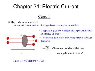
Chapter 24: Electric Current
Chapter 24: Electric Current. Definition of current. A current is any motion of charge from one region to another. Suppose a group of charges move perpendicular to surface of area A. The current is the rate that charge flows through this area:. Current. Units: 1 A = 1 ampere = 1 C/s.

Chapter 24: Electric Current
E N D
Presentation Transcript
Chapter 24: Electric Current • Definition of current A current is any motion of charge from one region to another. • Suppose a group of charges move perpendicular • to surface of area A. • The current is the rate that charge flows through • this area: Current Units: 1 A = 1 ampere = 1 C/s
Microscopic view of current Current
Microscopic view of current (cont’d) • In time Dt the electrons move a distance • There are n particles per unit volume that carry charge q • The amount of charge that passes the area A in time Dt is • The current I is defined by: Current • The current density J is defined by: Current per unit area Units: A/m2 Vector current density
Ohm’s law • The current density J in a conductor depends on the electric field E and • on the properties of the material. • This dependence is in general complex but for some material, especially • metals, J is proportional to E. V/A ohm Ohm’s law Resistivity Substance r (Wm) Substance r (Wm) silver graphite silicon copper glass gold teflon steel
Conductors, semiconductors and insulators • Good electrical conductors such as metals are in general good heat • conductors as well. In a metal the free electrons that carry charge in electrical conduction also provide the principal mechanism for heat conduction. • Poor electrical conductors such as plastic materials are in general poor • thermal conductors as well. • Semiconductors have resistivity intermediate between those of metals • and those of insulators. Resistivity • A material that obeys Ohm’s law reasonably well is called an ohmic • conductor or a linear conductor.
Resistivity and temperature • The resistivity of a metallic conductor nearly always increases with • increasing temperature. reference temp. (often 0 oC) temperature coefficient of resistivity Resistivity Material Material a (oC)-1 a (oC)-1 aluminum iron lead brass manganin graphite silver copper
Resistivity vs. temperature • The resistivity of graphite decreases with the temperature, since at higher • temperature more electrons become loose out of the atoms and more mobile. • This behavior of graphite above is also true for semiconductors. • Some materials, including several metallic alloys and oxides, has a property • called superconductivity. Superconductivity is a phenomenon where the • resistivity at first decreases smoothly as the temperature decreases, and then • at a certain critical temperature Tc the resistivity suddenly drops to zero. Resistivity r r r T T T Tc semiconductor superconductor metal
Resistance • For a conductor with resistivity r, the current density J at a point where • the electric field is E : • When Ohm’s law is obeyed, r is constant and independent of the magnitude • of the electric field. • Consider a wire with uniform cross-sectional area A and length L, and let • V be the potential difference between the higher-potential and lower-potential • ends of the conductor so that V is positive. Resistance resistance 1 V/A=1W I A L • As the current flows through the potential difference, electric potential • is lost; this energy is transferred to the ions of the conducting material • during collisions.
Resistance (cont’d) • As the resistivity of a material varies with temperature, the resistance of a • specific conductor also varies with temperature. For temperature ranges that • are not too great, this variation is approximately a linear relation: • A circuit device made to have a specific value of resistance is called a • resistor. Resistance I I V V semiconductor diode resistor that obeys Ohm’s law
Example: Calculating resistance • Consider a hollow cylinder of length L and inner • and outer radii a and b, made of a material with • r. The potential difference between the inner and • outer surface is set up so that current flows radially • through cylinder. b • Now imagine a cylindrical shell of radius r, length L, • and thickness dr. a Resistance r A
Complete circuit and steady current • For a conductor to have a steady current, it must be part of a path that • forms a closed loop or complete circuit. + + + + + + + + I - I I - - - - - - - Electromotive Force (emf) and Circuit
Maintaining a steady current and electromotive force • When a charge q goes around a complete circuit and returns to its • starting point, the potential energy must be the same as at the beginning. • But the charge loses part of its potential energy due to resistance in a conductor. • There needs to be something in the circuit that increases the potential energy. • This something to increase the potential energy is called electromotive force • (emf). Units: 1 V = 1 J/C • Emf makes current flow from lower to higher potential. A device that • produces emf is called a source of emf. Electromotive Force (emf) and Circuit source of emf • If a positive charge q is moved from b to a inside the • source, the non-electrostatic force Fn does a positive • amount of work Wn=qVab on the charge. • This replacement is opposite to the electrostatic force • Fe, so the potential energy associated with the charge • increases by qVab. For an ideal source of emf Fe=Fn • in magnitude but opposite in direction. • Wn=qe = qVab, so Vab=e=IR for an ideal source. b a - + current flow
Internal resistance • Real sources in a circuit do not behave ideally; the potential difference • across a real source in a circuit is not equal to the emf. Vab=e– Ir (terminal voltage, source with internal resistance r) • So it is only true that Vab=E only when I=0. Furthermore, e–Ir = IR or I = e/ (R + r) Electromotive Force (emf) and Circuit
Real battery R c d c d I Battery r a b b a + − Electromotive Force (emf) and Circuit • Real battery has internal resistance, r. • Terminal voltage,ΔVoutput= (Va−Vb) = − I r.
Potential in an ideal resistor circuit c d a b Electromotive Force (emf) and Circuit b a c d b
Potential in a resistor circuit in realistic situation c d R I Battery r b a b a - + Electromotive Force (emf) and Circuit r V R - + e I r IR 0 d c b a a b
Electric power • Electrical circuit elements convert electrical energy into • heat energy( as in a resistor) or • light (as in a light emitting diode) or • work (as in an electric motor). • It is useful to know the electrical power being supplied. • Consider the following simple circuit. Energy and Power in Electric Circuit dUe is electrical potential energy lost as dQ traverses the resistor and falls in V by ΔV. R Electric power = rate of supply from Ue.
Power output of a source • Consider a source of emf with the internal resistance r, connected by • ideal conductors to an external circuit. • The rate of the energy delivered to the external circuit is given by: • For a source described by an emf E and an internal resistance r - + Energy and Power in Electric Circuit battery (source) net electrical power output of the source I I rate of electrical energy dissipation in the internal resistance of the source a + b - rate of conversion of nonelectrical energy to electrical energy in the source headlight (external circuit)
Power input of a source • Consider a source of emf with the internal resistance r, connected by • ideal conductors to an external circuit. total electrical power input to the battery - + battery small emf I rate of conversion of electrical energy into noneletrical energy in the battery rate of dissipation of energy in the internal resistance in the battery I Energy and Power in Electric Circuit Fn a + b - + v alternator large emf
Examples: A ammeter a b A V : measures current through it : measures pot- ential difference Electromotive Force (emf) and Circuit voltmeter V
Drude’s model Electric Conduction
Drude’s model (cont’d) Electric Conduction
Drude’s model (cont’d) Electric Conduction
To find the resistance at 1000 C: But so we have : Exercise 1 Calculate the resistance of a coil of platinum wire with diameter 0.5 mm and length 20 m at 20 C given =11×10−8 m. Also determine the resistance at 1000C, given that for platinum =3.93×10⁻³ /°C. Where we have assumed l and A are independent of temperature - could cause an error of about 1% in the resistance change.
Exercise 2 A 1000 W hair dryer manufactured in the USA operates on a 120 V source. Determine the resistance of the hair dryer, and the current it draws. The hair dryer is taken to the UK where it is turned on with a 240 V source. What happens? This is four times the hair dryer’s power rating – BANG and SMOKE!