The medipix3 TSV project
200 likes | 548 Views
The medipix3 TSV project. Jerome Alozy and Michael Campbell CERN Geneva, Switzerland 10 April 2013 2 nd AIDA Annual meeting. Outline. Summary of project plans Medipix3 – designed for TSVs LETI process reminder Status of project Some key numbers for the LETI process Future plans.

The medipix3 TSV project
E N D
Presentation Transcript
The medipix3 TSV project Jerome Alozy and Michael Campbell CERN Geneva, Switzerland 10 April 2013 2nd AIDA Annual meeting
Outline Summary of project plans Medipix3 – designed for TSVs LETI process reminder Status of project Some key numbers for the LETI process Future plans
Phase 1: TSV processing of Medipix3 wafers - Process 10 wafers in CEA LETI - Separated in 3 lots in order to improve the process step by step - Third lot gave good preliminary results! Phase 2: Hybridization of the TSV processed chips - Chip pick up and selection of KGD - Preparation of sensors - Flip chip to KGD - Test of single assemblies Phase 3: Demonstrator Module - Mount single chip assembly on appropriate support cards - Demonstrate multichip module operations * LETI contract supported at the level of 14% by AIDA Other partners: Alice, LCD, Medipix3 Collaboration Project Outline
Reminder of LETI Process • Front Side UBM • TiNiAuDeposition • Litho UBM • UBM etch UBM • Bonding / Thinning • Bonding • Grinding/edgedicing • CMP Si • Back Side: TSV Last + RDL + Passivation + UBM • Litho TSV • TSV AR2 etch • SiONconfdeposition • Etch back • SEED TiCu • Litho RDL • ECD Cu • Litho PASSIV • TiNiAudeposition • Litho UBM • UBM etch • Debonding / Dicing TSV RDL UBM
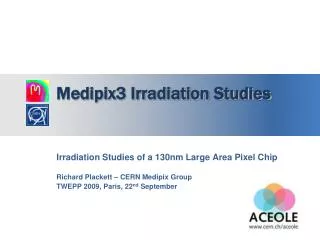
Medipix3 ready for Through Silicon Vias All IO logic and pads contained within one strip of 800mm width All IO´s have TSV landing pads in place Permits 4-side butting 94% sensitive area
Wafer Layout Approximatively 100 chips per wafer
RDL design (Timo Tick) Front side Electrical tests area Back side Electrical tests area Complete map Metrology boxes Alignment Marks Active chip RDL details
Medipix 3 projectresults / electrical tests (non exhaustive) • UBM/ Al contact resistance P02 P03 P01 Cumulative resistance UBM/Alu Mean value : ~ 150 mohms • Conclusions: Isolation between UBM lines OK Alu/UBM contact resistanceis OK
Medipix 3 projectresults / electrical tests (non exhaustive) 3.60 W± 1.9 % (1s) 1.23 W± 3.6 % (1s) • 2 TSV chain resistance (by Vdd) P01 P02 P03 • 2 TSV chain resistance (by Vss) P03 P01 P02 D. Henry, LETI • Conclusions: Uniform distribution of values no comparizonwithreference value possible
Medipix 3 projectresults / electrical tests (non exhaustive) 50 mW± 14 % (1s) Ileak < 1 E-06A • Kelvin TSV Mean value P03 P02 P01 Kelvin3D (Specs < 1 Ohm/TSV) / Yield: 96% Kelvin3D (Specs < 1 Ohm/TSV) / Yield: 100% • Insulation between 2 TSV (1 connected TSV to M1 & 1 non connected) – Applied voltage : 1V P02 P03 P01 • Conclusions: Insulation issue on P01 & P02 / Root cause identified Correction on P03 D. Henry, LETI
Dicing/chip pickup issues • Chips Dicing & boxes packaging • First delivered wafers : • Metal delaminations on front side • High chipping on the edges • Chips breaking during pick out process • Tape residues on pixel side Tape residues High chipping + pad delamination • Need to develop an optimized dicing process : • DISCO collaboration Backsidechipping
Dicing/chip pickup issues • Dicing trials on DISCO plant (Munchen) • Taping of BGA side on the tape • UV tape • Fine blade • High Blade rotation • Low Blade speed • Pixel side observations • Chip I4 • Lower chipping compare to previous dicing • Every defects localized on dicing streets
Dicing/chip pickup issues • Pixel side observations • Chip I4 • BGA side observations • Higher chipping than on the pixel side contact with tape • All defects localized on the dicing streets polymer seal ring effect
Test setup at CERN • Test set-up : • Test board realize the interface between Medipix3 chip and readout interface • Test socket is embedded on test board to establish contact to the bga pads of the chip • We are using a custom readout interface (USB) common to most of MEDIPIX chip family Test board Test socket Readout interface • Test samples • LETI sent a complete GELPAK of 16 diced chips. (DISCO dicing) • Parts are from IBM wafer # AZNW5VH, at CERN it was identified as Wafer # 24
Noise floorcomparison • We could notice only a slight difference Before TSV After TSV
CEA-LETI TSV process - key numbers • AR (wafer thickness to TSV diameter) max 3:1 • Minimum TSV pitch 80um • Minimum TSV diameter 40um • RDL min track width 20um • RDL min track space 40um • RDL thickness range 2um to 12um Cu • Front side UBM min space 30um • Front side UBM min width 20um (For ref MPIX3 25um diameter on 55um pitch) • Back side UBM min space 30um • Back side UBM min width 20um • TSV typical resistance 50mohm (60um on 120um thickness) • TSV typical isolation >= 1Gohm • Resistance UBM toAl pad 150mohm for 25um diameter.
Project status and future work AIDA project • First 2 assemblies have been received (VTT/Advacam) • More to follow soon (need to bump sensors) • Test card ready • Low melting point BGA spheres ordered Future work (Medipix3 Collaboration/LCD) • Process a further 6 Medipix3RX wafers at CEA • Cover large area • Smallpix edgeless chip design