Download
1 / 28
280 likes | 316 Views
CLICpix2 project outline, updates on analog & digital parts, power distribution, updated pixel logic, readout architecture, and current status. Learn about improvements and advancements in this cutting-edge design project.

E N D
Pierpaolo Valerio Edinei Santin 02.06.2015 CLICPIx2 design and TSV project status
Outline • CLICpix2 • Overview • Analog part • Digital part • Status • TSV project • Status
CLICpix2 Overview • CLICpix2 is a revised and improved version of the CLICpix prototype currently being designed • Main improvements: • Larger pixel matrix (64x64 128x128 pixels) • Longer counters (8 bits ToA + 5 bits ToT) • 13bits ToA/counting with no ToT mode of operation • Improve isolation of sensitive analog nodes • Improve the communication logic • Include a bandgap block Die photo
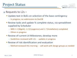
Work plan • Different analog and digital tasks were identified and split between the design team • The schedule is feasible, but we want to prioritize having a well verified design before submission • There are submissions through IMEC every two weeks. Booking a run requires only a two-week notice.
Outline • CLICpix2 • Overview • Analog part • Digital part • Status • TSV project • Status
Analog frontend updates • Feedback networks of the CSA were slightly downscaled to reduce their area • CSA and calibration DAC topologies kept the same • Study on the two-stage comparator topology pointed out that it has better gain-speed tradeoff than a three-stage one. Hence, we didn’t change its topology
Analog frontend layout • Width is 2 um shorter than previous layout • Substrate isolation with deep n-well • Better physical separation of the building blocks 12 um 25 um
Substrate Isolation • VSSA isolated from VSSD with deep n-well • Noise propagation from noisy digital substrate to VSSA is highly attenuated A B Digital Digital Analog
Floorplan comparison Before Now • Better physical separation of the building blocks, which means less crass-talk among them due to routing
Pixels mirroring Right analog pixel of the double column Left analog pixel of the double column • Left and right analog pixels are mirrored to ensure symmetrical routing, and also to enclose the deep n-well
Analog & Digital Power Distribution VSSD PRELIMINARY • Ultra-thick metal (Rsh ≈ 5 mΩ/sq) used for power distribution • Maximum IR drop on VDDA/VSSA is ~6 mV for the pixels at the top of the matrix 2 um VSSA 2 um 25 um 3.5 um VDDA 2.5 um VDDD 11
Outline • CLICpix2 • Overview • Analog part • Digital part • Status • TSV project • Status
Updated pixel logic • The logic has been updated and resynthesized • It is slightly bigger than before: 200 by 25.2 µm for a group of 16 pixels (it was 200 by 22.4 µm before) • The additional area takes the place of a more compact analog side layout
Updated pixel logic • The counters now have increased depth: • 5 bits ToT (up from 4) • 8 bits ToA / event counting (up from 4) • A new acquisition mode can be selected, combining the two counters as a single 13 bits ToA / event counting register with increased dynamic range • A small readout bug has been solved, allowing a faster readout when the compression feature is enabled • Overflow control is still applied to all the counters in all modes of operations
Readout logic • The current readout architecture works as intended, but it’s difficult to use a fast clock with it due to synchronization issues • In order to make it easier to design the DAQ board and firmware, it’s better to use a higher clock frequency with a clock recovery mechanism (8/10 bit encoding) • Due to the lack of a PLL block, we will use the acquisition clock (100 MHz) as the input clock for control signals and have a second clock (≥ 320 MHz) only used for the readout command 15
Parallel readout • In order to use clock recovery for the readout, the chip needs to send data at a faster speed (≥640 Mbit/s) • Sending a very fast clock to the pixel matrix is not possible due to the clock distribution tree Efficiency # columns Occupancy • The chip can thus be configured to read multiple columns in parallel (using a slower clock) and serialize the data at the output • The efficiency loss in terms of readout time is limited at the expected occupancies 16
Other readout blocks • A 8 to 10 bit encoder is included in order to allow for clock recovery and AC coupling for the output • A Double Data Rate (DDR) block will be implemented to limit the needed clock frequency. This way a 320 MHz clock is enough to output data at 640 Mbits/s • A clock divider is used to have a slower clock to be distributed to the pixel matrix; the undivided clock is only used for the output serializer 17
Outline • CLICpix2 • Overview • Analog part • Digital part • Status • TSV project • Status
Current status • Extracted simulations of the analog frontend are being carried out to verify specifications fulfillment • The pixel logic has been fully synthesized, simulated and validated • The digital periphery (command interpreter, power pulsing logic…) is mostly unchanged from the previous chip • The readout logic is being designed and simulated but it has yet to be fully synthesized 19
Outline • CLICpix2 • Overview • Analog part • Digital part • Status • TSV project • Status
Medipix chips related TSV developments – Third run (3D06)Inputs from G. Pares (CEA LETI) and J. Alozy (CERN) • Launched in CEA LETI (Grenoble) in July 2014 - Proof of concept of TSV last with TIMEPIX3/Medipix3RX wafers thinned to ~ 50μm - Reuse the TSV bricks maturated with 3D01 (Medipix3) and 3D05 (Medipix3RX) but adapted to such thickness • Lot # D14S0398 (Medipix3RX) started in July 2014: First lot has been processed using 2 Medipix3RX that is well known and its TSV compatibility has been proven • P01-W145-AJPFVDH (TSV ᴓ 60 μm, depth 50 μm) • P02-W129-ANPG8JH (TSV ᴓ 60 μm, depth 50 μm) • +P05-W127-AKPGALH (rework from 3D05 120 μm thick) • Lot# D14S0705 (Timepix3) started in September 2014: Second lot has been processed using only 2 Timepix3, since limited number of Timepix3 wafer candidates are available. First TSV trials using TIMEPIX3 chip • P04-W006-AIPW0DH (TSV ᴓ 60 μm, depth 50 μm) • P03-W007-A2PVZDH (TSV ᴓ 60 μm, depth 50 μm)
Medipix chips related TSV developments – Third run (3D06) • Lot # D14S0398 (Medipix3RX): • Front side Under Bump Metallization and thinning to ~50μm have been done without problems • There were some difficulties in the TSV fabrication, issues with arcing during Hard Mask etching. • After Redistribution Layer Lithography process a visual inspection of the TSV was done and some residual polymers were discovered, probably generated between seed deposition and Lithography steps. • Despite of all these issues the first electrical results are very good (daisy chain tests). A minor leakage current was observed but it is comparable to previous lots. • Wafers have been sent out for debonding and dicing
Medipix chips related TSV developments – Third run (3D06) • Lot # D14S0705 (Timepix3) : • There are still issues with HM etching but a new recipe with lower power and higher pressure has been successfully tested at PMD etch limiting additional arcing during that process. • The lot has been electrically tested (we wait for the test results from LETI) and sent to EGV (Austria) for debonding from temporary carrier and bonding on dicing tape. They are about to be received by DISCO (Germany) for dicing (dicing probably during the week of the 1st June 2015). • After dicing both lots will be returned to CEA LETI for inspection and ejection from dicing tape. • Finally the diced chips will be returned to CERN for validation tests (before end of June)
Pad geometry • There is only a 2 um spacing between the opening and the edge of the pad, but the opening is big enough for electroplating • An added aluminium “tail” can increase the capacitance to a HVCMOS sensor 14 um 8 um 12 um 10 um 22.5 um 26
Medipix chips related TSV developments – Third run (3D06) • Lot # D14S0705 (Timepix3) : • Some dimensions of the pixel pads are smaller than Medipix3/3RX. Making the front side UBM process more sensitive to misalignment. Due to that P03 Litho has to be reworked. Final UBM pixel diameter =24μm Before process Post Litho After rework of Litho Post Etch On this lot some residues of UBM etching remains at the edges of the wafer SEM image: Better view of the final topology
Medipix chips related TSV developments – Third run (3D06) • Lot # D14S0705 (Timepix3) : Micro-Acoustic Inspection of the wafer bonding to its temporary carrier. No defects