Download
1 / 10
100 likes | 195 Views
Impact parameters in p11.07. Daniel Bloch + D.Gelé, S.Greder, I. Ripp-Baudot (IReS Strasbourg). Compare on run 152422 p10.15 (normal processing, using 60000 events) and p11.07 (reprocessed by Suyong, 90000 events)

E N D
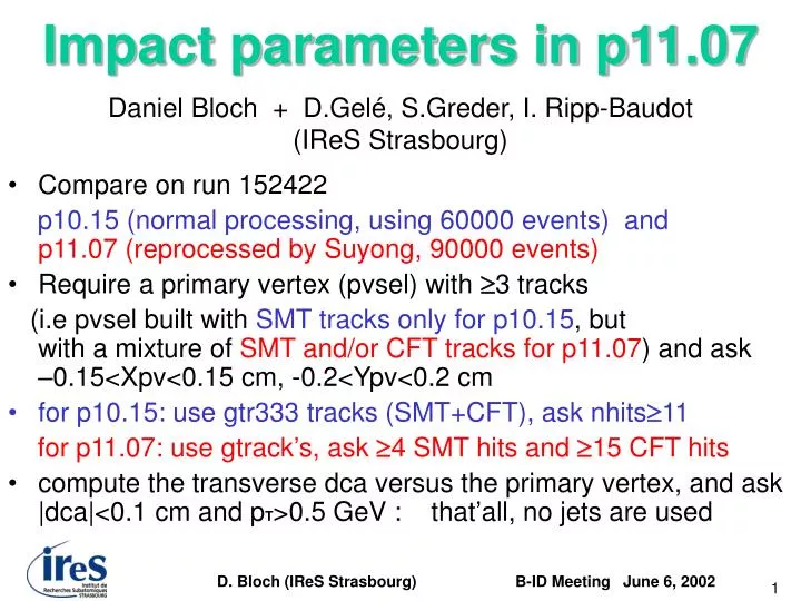
Impact parameters in p11.07 Daniel Bloch + D.Gelé, S.Greder, I. Ripp-Baudot (IReS Strasbourg) • Compare on run 152422 p10.15 (normal processing, using 60000 events) and p11.07 (reprocessed by Suyong, 90000 events) • Require a primary vertex (pvsel) with 3 tracks (i.e pvsel built with SMT tracks only for p10.15, but with a mixture of SMT and/or CFT tracks for p11.07) and ask –0.15<Xpv<0.15 cm, -0.2<Ypv<0.2 cm • for p10.15: use gtr333 tracks (SMT+CFT), ask nhits11 for p11.07: use gtrack’s, ask 4 SMT hits and 15 CFT hits • compute the transverse dca versus the primary vertex, and ask |dca|<0.1 cm and pT>0.5 GeV : that’all, no jets are used D. Bloch (IReS Strasbourg)
p11.07 p10.15 X X The primary vertex resolution is much better : 60 μm in p11.07110 μm in p10.15 (cm) Y Y (cm) D. Bloch (IReS Strasbourg)
The mean dca resolution is improved : 50 μm in p11.07, 90 μm in p10.15 (cm) D. Bloch (IReS Strasbourg)
Then, consider the quantity pSCAT = p sin³´²θ which describes multiple scattering effects in the transverse plane • Split in different pSCAT bins and in each bin: take the mean computed dca error σdcaand fit the dca/σdca distributions (with a Gaussian and 2 exponential tails) • Define the “fitted” error σFIT = σdca the width of the previous Gaussian D. Bloch (IReS Strasbourg)
the dca error is parameterised asσFIT = a/[p sin³´²θ] + b asymtotic resolution ~20 μm in p11.07 and~50 μm in p10.15 red dots: σFITblue square: σDCA σ (μm) σ(μm) p11.07 p10.15 p sin³´²θ (GeV) D. Bloch (IReS Strasbourg)
quite similar dependence in p10.15 for run 152422 or for all muon+jet runs 144000-151000 red dots: σFITblue square: σDCA σ(μm) σ (μm) p10.15 p10.15 p sin³´²θ (GeV) D. Bloch (IReS Strasbourg)
The correction factor to be applied on the computed dca error is 1.06 in average in p11.07, but it is a factor two in p10.15, and this is mometumangle dependent σFIT/σdca p11.07 p10.15 p sin³´²θ (GeV) D. Bloch (IReS Strasbourg)
The quadratic difference between the fitted and computed dca error is also momentumangle dependent, but is much smaller in p11.07 (μm) p11.07 p10.15 (μm) quadratic difference σFIT -σdca p sin³´²θ (GeV) D. Bloch (IReS Strasbourg)
The significance has a resolution of 1 after these corrections D. Bloch (IReS Strasbourg)
Summary Very nice prospects with p11.07 ! Correction factor depending on p sin³/²θ to be applied D. Bloch (IReS Strasbourg)