Download
1 / 31
310 likes | 512 Views
Low-Power, Low-Phase Noise SiGe HBT Static Frequency Divider Topologies up to 100 GHz. Ekaterina Laskin, Sean T. Nicolson, Sorin P. Voinigescu University of Toronto, Canada Pascal Chevalier, Alain Chantre, Bernard Sautreuil, STMicroelectronics, France. Outline. Motivation

E N D
Low-Power, Low-Phase Noise SiGe HBT Static FrequencyDivider Topologies up to 100 GHz Ekaterina Laskin, Sean T. Nicolson, Sorin P. Voinigescu University of Toronto, Canada Pascal Chevalier, Alain Chantre, Bernard Sautreuil, STMicroelectronics, France
Outline • Motivation • Static divider topology • Fabrication technologies • Test setup and results • Conclusion Paper Number 12.3
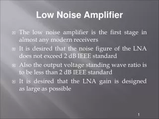
Motivation • Applications at 80 GHz: • Phase-locked loop • Radio circuits • Comparison of divider topologies • Technology benchmark Paper Number 12.3
Static Divider Topology • On-chip transformer and matching • Toggle flip-flop, 50 Ω output buffer • 2 different latch designs implemented Paper Number 12.3
Integrated Transformer primary 30µm • Stacked design, top 2 metals over substrate • 30µm square, 1µm spacing, 2µm metal width secondary Paper Number 12.3
Transformer Model primary k secondary substrate model • Model extracted from geometry using ASITIC • π - network includes substrate model • k = 0.855 is achieved Paper Number 12.3
Input Network Simulation • Divider input matched 40 – 100 GHz • Transformer operational up to 100 GHz Paper Number 12.3
Latch Design 1 – w/o input EF • ECL latch • Inductive peaking • No split load • Self-biased • Resistive input biasing Paper Number 12.3
Latch Design 2 – with input EF • Double-EF input buffer Paper Number 12.3
300 300 250 250 f 200 200 MAX f MAX 150 150 f T f 100 100 T 50 50 0 0 0.1 1 10 0.1 1 10 2 2 m J (mA/ m ) m J (mA/ m ) C C Implementation • Both dividers fabricated in 2 SiGe processes: BiCMOS9 BipX Paper Number 12.3
Fabricated Dividers Paper Number 12.3
Fabricated Dividers Paper Number 12.3
Fabricated Dividers Paper Number 12.3
Fabricated Dividers Paper Number 12.3
Fabricated Dividers 515μm × 473μm 3.3 V 145 mW 502μm × 360μm 3.3 V 122 mW Paper Number 12.3
Test Setup 0 - 50 GHz: 50 - 75 GHz: 75 - 100 GHz: Paper Number 12.3
80 75 BipX 70 65 Divider SOF (GHz) 60 55 Divider with EF 50 BiCMOS9 Divider w/out EF 45 40 220 240 260 280 300 (GHz) Process f MAX Measurement Results • Divider self-oscillation frequency: BipX1 BipX2 Paper Number 12.3
20 10 0 -10 Input Power [dBm] -20 BipX, w/o EF BipX, w/ EF -30 BiCMOS9, w/o EF -40 BiCMOS9, w/ EF -50 10 20 30 40 50 60 70 80 90 100 Input Frequency [GHz] Sensitivity Curves 25 °C Paper Number 12.3
20 10 0 -10 Input Power [dBm] -20 25 °C 50 °C -30 100 °C -40 -50 10 20 30 40 50 60 70 80 90 100 Input Frequency [GHz] Sensitivity Curves Paper Number 12.3
Divider Phase Noise Input Output • 100 GHz • -90.4 dBc/Hz @ 100 kHz offset • 50 GHz • -96.4 dBc/Hz @ 100 kHz offset • Phase noise -6 dB with frequency halving Paper Number 12.3
-30 -40 -50 Further Improvements 20 MOS-HBT 10 0 -10 Input Power [dBm] HBT only -20 BiCMOS9, HBT only BiCMOS9, MOS-HBT BipX, HBT only 10 20 30 40 50 60 70 80 90 100 Input Frequency [GHz] Paper Number 12.3
100 [9] 90 [6] 80 This Work [2] 70 Divider SOF [GHz] [8] 60 InP This Work CMOS 50 [7] SiGe 40 [5] 30 100 200 300 400 500 Technology fT [GHz] Comparison to Previous Work Paper Number 12.3
Conclusion • 2 SiGe static dividers designed and analyzed in 2 technologies • Designed divider operates up to 100 GHz • Features an integrated transformer operating at 100 GHz • Ideal phase noise behaviour • Low power Paper Number 12.3
Thank You Paper Number 12.3
Back-up Slides Paper Number 12.3
50-Ω Output Buffer Paper Number 12.3
300 300 250 250 200 200 f f MAX MAX 150 150 f T 100 100 f T 50 50 0 0 0.1 1 10 0.1 1 10 I (mA) I (mA) C C BipX Process Splits BipX2 BipX1 Paper Number 12.3
80 BipX 75 70 65 Divider SOF (GHz) 60 55 BiCMOS9 Divider with EF 50 Divider w/out EF 45 40 170 190 210 230 250 270 Process f (GHz) T Measurement Results • Divider self-oscillation frequency: BipX2 BipX1 Paper Number 12.3
Measurement Results Paper Number 12.3
Source Phase Noise @ 100GHz Paper Number 12.3
BiCMOS Divider Paper Number 12.3