Low-Frequency Versatile Wireless Power Transfer
Low-Frequency Versatile Wireless Power Transfer. Osman Salem, Alexey Guerassimov , and Ahmed Mehaoua University of Paris Descartes – LIPADE Division of ITCE, POSTECH, Korea Anthony Marcus and Borko Furht ,

Low-Frequency Versatile Wireless Power Transfer
E N D
Presentation Transcript
Low-Frequency Versatile Wireless Power Transfer Osman Salem, Alexey Guerassimov, and Ahmed Mehaoua University of Paris Descartes – LIPADE Division of ITCE, POSTECH, Korea Anthony Marcus and BorkoFurht, Department of Computer and Electrical Engineering and Computer Science, Florida Atlantic University Jonathan David 2013 IEEE International Conference onCommunications, pp.4373,4378, 9-13 June 2013
The Need for Improvement • Non-rechargeable batteries only support implants with extremely low power consumption • Pacemaker must be replaced every 5-8 years by invasive surgery, battery occupies 90% of device volume • RF radiation hazard and tissue absorption are concerns in wireless power technologies • An accurate impedance matching network is required for efficient power delivery • Power scavenged by bio-surroundings is still only in the nano-watt range
The Need for Improvement • Cardiac pacemakers • Retina prostheses (emerging technology) • Brain-computer interfaces • Drug delivery systems • Smart orthopedic implants
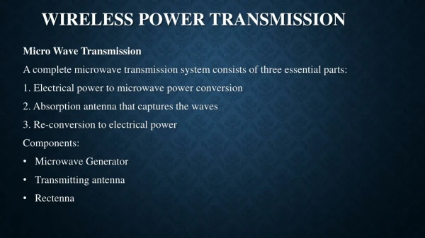
The Solution • Use of a low-frequency electrical power transfer technology • Wireless power transfer has existed, however medical trials have used devices operating in the GHz range
How does it work? • Magnetic field is generated by rotating permanent magnets • An inductive coil at the receiving end is charged
What are the advantages? • Radiation hazard completely avoided • Resistance instead of reactance dominates the impedance of the coil due to the low frequency • Resistance is less likely to change based on the application • More materials can be used for the receiving coil • The magnetic field can penetrate various materials
Design of Rotor and Coil • Magnetization of disk magnets is perpendicular to the surface • Polarization on the head is alternated to create an alternating magnetic field • Diameter of the coil matters • Too small and some magnetic flux is lost • Too large and multiple magnets will affect coil
Delivered Power • Power delivered to the implant from the external source is reduced mainly by three forces • Power consumed to rotate magnets • Drag caused by induced current in receiving coil • Power lost due to conversion from AC to DC
Delivered Power • Equivalent circuit is shown • In RF applications, wL is much greater than RS and RL • Choosing a suitable capacitor value is difficult in practice
Efficiency • Characterized by the ratio of delivered AC power at the load to the total power consumed by the DC motor • Motor in study consumes 1.445W, with a current of 0.170A • Extra power consumed is due to the receiving coil • Efficiency can be hurt by external factors • Human body (replicated with saline solution in studies) • External housing (medical grade stainless steel, aluminum)
Drawbacks • Device is bulky due to the size of the antenna • No wireless communication transfer through power delivery system • RF power transfer has this capability
Shortfalls of the Study • Many different materials could have been used to evaluate power transfer • Study seemed to be very basic • No comparison against efficiency of RF power transmission
Conclusions • Low-frequency wireless power transfer provides an efficient way to power medical implants • Coupling circuitry is not needed • Will work in a variety of conditions • Unfortunately, resulting device is large due to receiving coil size • Unknown how it compares to RF technologies
Near-Threshold OOK-Transmitter with Noise-Cancelling Receiver Mai Abdelhakim, Leonard E. Lightfoot, Jian Ren, Tongtong Li Department of Electrical & Computer Engineering, Michigan State University Air Force Research Laboratory, Wright-Patterson Air Force Base Jonathan David 2013 IEEE International Conference onCommunications, pp.1720,1724, 9-13 June 2013
The Need for Improvement • Power consumption is a highly critical requirement for future wireless body-area network sensors • Of all the circuit components on system-on-chip designs, the wireless transceiver usually consumes the most power (70-80%) • Design considerations make development of an energy efficient WBAN difficult • Reliability and noise immunity are key requirements aside from power consumption
The Need for Improvement • Body absorption can affect the signal-to-noise ratio of the transceiver • Noisy blocks (like the ADC or a switching power supply) in the SoC can increase bit-error rates • Affects OOK, which has difficulty discerning between coupling noise and small-signal data inputs
The Solution • Introduce a MICS (402-405MHz) transciever that operates in the near threshold domain (~.65V) • Remains energy efficient by using high frequency and low voltage • Noise sensitivity reduced by using a super-regenerative oscillator • Noise injections appears common-mode
Transceiver Architecture • OOK (on-off keying) is used • Simple, highly sensitive, and low-power • Received signal • Sent through low-noise amplifier and DCO • Structure referred to as a super regenerative receiver • A replica SRR is used to mitigate on-chip noise • Generates common-mode reference envelope for comparisons • Envelope detector receives signal from SRR • Signal output at a maximum of -16 dBm
Near-Threshold Transmitter • Uses sub-harmonic injection locking and edge combining • Eliminates the use of a PLL • Power hungry • Slow settling time • Prevents use of aggressive duty cycling
Sub-Harmonic Injection Locking • Sub-harmonic injection occurs when an incident frequency is a sub-harmonic of the oscillator free-running frequency • Used for frequency synthesis and phase lock • As the division ratio increases, the noise rejection ability decreases
Near-Threshold Operation • Improves energy efficiency • Increases signal to noise ratio, resulting in larger oscillator phase noise
Spur Suppression • Injected signal is typically a square wave, which consists of large harmonic content • The N-th harmonic locks the oscillator, while other harmonics appear on the output as spurs • Decreasing the locking range reduces the SNR of the spurs • Decreasing the locking range decreases the loop bandwidth • Easier to lose lock • Time to lock on a signal is increased
Super-Regeneration • Exploits the non-linear gain at the startup of an LC oscillator • Exponential time-dependent gain is achieved for a short period of time, resulting in a large magnitude regardless of the input signal • Workings of this are not immediately obvious • To properly take advantage of this, a very high-Q filter is needed • Luckily, the SRR “tank” circuit can be tuned to create this filter!
Super-Regeneration • Simplified, the digitally controlled oscillator is set in Q-enhancement mode to select a band of interest • Conductance of the DCO is switched from + to -, which increases the tank current • Increased tank current achieved super-regeneration, and the selected signal is amplified
Shortfalls of the Study • Operation at close to threshold voltage renders circuitry very susceptible to voltage spikes • Locking range of sub-harmonic injection when compared to a PLL
Conclusions • A low-power, noise-cancelling transceiver is possible with the proposed device • Sub-harmonic injection locking provides a viable, low-power alternative for a PLL • Super-regeneration allows for low-power amplification • Received data is accurate • Is operating at such a low voltage dangerous?