Download
1 / 16
160 likes | 258 Views
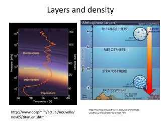
This paper presents depth profiles and thermal desorption studies of hydrogen isotopes in plasma-facing carbon tiles from the JT-60U tokamak. Various aspects, such as hydrogen retention, isotope exchange, and diffusion profiles, are analyzed using techniques like IR and NMR spectroscopy. The study reveals insights into hydrogen behavior in different temperature regimes and its implications for plasma-facing materials. The impact of energetic H+ and H2 neutrals on hydrogen retention and depth profiles is also discussed.

E N D
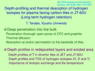
9th ITPA meeting on SOL/divertor physics, Garching, May 7-10, 2007 Depth-profiling and thermal desorption of hydrogen isotopes for plasma facing carbon tiles in JT-60U(Long term hydrogen retention)T. Tanabe, Kyushu University ☆Deep penetration into the bulk Penetration thorough open pores of CFC and graphite Thermal diffusion Absorption at and/or permeation to the backside of tiles. ☆Depth profiles in redeposited layers and eroded area Depth profiles of T in divertor tiles of JET and JT-60U Depth profiles and TDS of hydrogen isotopes (H, D and T) Importance of Isotopic exchange and tile temperature
A:C-H film ever produced Determined by ○ : IR ● : NMR ▲ :EELS Hydrogen solubility Hydrocarbons are unstable above 800K Hydrogen solubility (very small) RT Gas Graphite(Solid) Liquid T. Tanabe et al., Journal of Nuclear Materials 313–316 (2003) 478–490
Hydrogen retention and depth profile under H+ and H2 exposure H2 and H0 All grains are under the same static pressure Keeping nearly the same level Above ~800K Isotope exchange becomes easier Below ~700K No diffusion into bulk or particles
JET tile : Cross section of cored hole in divertor base tile :BN4 Surface Tritium activity is mostly on the plasma facing surface Probably due to temperature difference
PSL intensity [PSL/mm2] Backs side of BN7 Stripes corresponding the woven structure of 2-D CFC Absroption of low energy (gaseous) tritium Cf. No stripes were observed on the front surface T. Tanabe et al., Journal of Nuclear Materials 313–316 (2003) 478–490
50 40 30 20 10 0 Tritium depth profile : observed by cross-sectional view of dome top tile in JT-60U divertor PSL intensity [PSL/mm2] Outside inside PSL intensity [PSL/mm2]
D/12C 0 H/12C 0 (H+D)/12C Thin deposits on outer dome wing NRA: D retention within 2.1mm~8.0 x 10¹⁶(/cm2) D/C ~ 2%(max) SIMS H retention within <2.1mm ~4.3 x 10¹⁶(/cm2) H/C at surface ~3.5 % NRA + SIMS(H+D)/C (<2.1mm)~1.2 x 10¹⁷(/cm2) (H+D)/C (<0.5mm)(H+D)/C~2.5% Y. Oya, Y. Hirohata, et al., J. Nucl. Mater. 313-316 (2003) 209 depth1.7mm -11- T. Hayashi et al. J. Nucl. Mater
TDS measurements Eroded area OD1 1400K Desorptionrate / 1019molecules・m-2・ s-1 Redeposits on ID3 1000K Total retention / 1022atoms・m-2 Redeposits on DM9 800K Temperature/K Sample position Bulk retention Temperature reduces D/H
D/H ~ 1.6 DM 800K D/H ~ 0.47 ID 1000K D retention H retention D/H << 5.1 (ratio of discharges numbers of DD/HH) → Replacement of D by H Redeposited layers on ID… Deposited at higher temp(1000K). Low D/HDM…Deposited at lower temp.(800K) High D/H (Less exchange) On the Inner Divertor 1000K Homogeneous distribution with (H+D)/C = 0.031Indicating Isotope exchange even in deep region owing to high temp.
Bulk retention given by H2 and H0 H2 and H0 Keeping nearly the same level Above ~800K Isotope exchange becomes easier Below ~700K No diffusion into bulk or particles
Substrate Redeposited process with hydrogen incorporation Higher heat load Temperature High Low HDmixing in the layers Addition of HH discharges Starting DD discharge After DD dischyarge Formation of redeposited layers Lower heat load HDmixing near boundary only Low Temperature
Substrate Hydrogen retention at eroded area Eroded area with high heat load (OD) Temperature High Starting DD discharges Termination of DD discharges No deposition High energy implantation Addition of HH discharges
Hydrogen retention and depth profile under exposure of energetic H+ and H2 neutrals All grains are under the same static pressure
Outer divertor Inner divertor 973K Baffle plates Dome 773K 623~673K 623K Base temp. 573K Inner divertor tile, ~1000 K Dome unit tile ~800 K Outer divertor tile ~1400 K Depth profiles of JT-60U divertor tiles Tile temperature monitored by TCs installed in the tiles Maximum Surface temperatures estimated by a finite element modeling K.Masaki, et.al., J.Nucl.Mater., 313-316 (2003) 514 Surface temperature increase DD discharges >> HH discharges Because NBI power of HH discharges ~ ½ of that of DD discharge