Download
1 / 58
620 likes | 869 Views
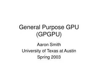
The Architecture and Evolution of CPU-GPU Systems for General Purpose Computing. Manish Arora Computer Science and Engineering University of California, San Diego. From GPU to GPGPU. GPU. GPGPU. SM. SM. Input Assembly. Frame Buffer Operations. Vertex Processing. Geometry Processing.

E N D
The Architecture and Evolution of CPU-GPU Systems for General Purpose Computing Manish Arora Computer Science and Engineering University of California, San Diego
From GPU to GPGPU GPU GPGPU SM SM . . . Input Assembly Frame Buffer Operations Vertex Processing Geometry Processing Shared Mem Shared Mem . . . L2 L2 Memory Controller Memory Controller Off-Chip Memory Off-Chip Memory Widespread adoption (300M devices) First with NVIDIA Tesla in 2006-2007.
Previous Generation Consumer Hardware1 GPGPU CPU SM SM Core Core . . . Shared Mem Shared Mem . . . Cache Hierarchy Cache Hierarchy L2 Last Level Cache Memory Controller Memory Controller Off-Chip Memory PCI Bridge 1 2006 – 2010 Off-Chip Memory
Current Consumer Hardware2 SM SM SM Core Core . . . Shared Mem Shared Mem Shared Mem . . . Cache Hierarchy Cache Hierarchy L2 Shared On-Chip Last Level Cache CPU GPGPU Memory Controller Off-Chip Memory 2 Intel Sandy Bridge AMD Fusion APUs 2011 - 2012
Our Goals Today • Examine the current state of the art • Trace the next steps of this evolution (major part) • Lay out research opportunities
Throughput Applications Energy Efficient GPUs Lower Costs Overheads Outline CPU only Workloads GPGPU Part 1 Part 6 Chip Integrated CPU-GPU Systems (Future Work) Part 2 Part 5 Tools Holistic Optimizations GPGPU Evolution Opportunistic Optimizations Emerging Technologies Part 3 Part 4 Power Temperature Reliability CPU Core Optimization Shared Components Redundancy Elimination Next Generation CPU – GPU Architectures
Part 1 Throughput Applications Energy Efficient GPUs Lower Costs Overheads Progression of GPGPU Architectures CPU only Workloads GPGPU Chip Integrated CPU-GPU Systems
GPGPUs - 1 • The fixed function graphics era (pre 2006) • Programmable vertex processors • Programmable pixel processors • Lots of fixed hardware blocks (assembly, geometry, z-culling…) • Non-graphics processing was possible • Represent user work as graphics tasks • Trick the graphics pipeline • Programming via graphics APIs • No hardware for bit-wise operations, no explicit branching… • Imbalance in modern workloads motivated unification • General purpose opportunity sensed by vendors
GPGPUs - 2 • The unified graphics and computing era (2006 - 2010) • Single programmable processor design • Explicit support for both graphics and computing • Computing specific modifications (IEEE FP Compliance and ECC) • Non-graphics processing easy • High level programming (C, C++, Python etc.) • Separate GPU and CPU memory space • Explicit GPU memory management required • High overhead to process on the GPU • Memory transfers over PCI • Significant customer market penetration
GPGPUs - 3 • Chip Integrated CPU-GPU era (2011 onwards) • Multicore CPU + GPGPU on the same die • Shared last level caches and memory controller • Shared main memory system • Chip Integration advantages • Lower total system costs • Shared hardware blocks improve utilization • Lower latency • Higher Bandwidth • Continued improvements in programmability • Standardization efforts (OpenCL and DirectCompute)
DRAM DRAM DRAM Contemporary GPU Architecture(Lindholm et al. IEEE Micro 2007 / Wittenbrink et al. IEEE Micro 2011) GPGPU CPU Memory Controller Memory Controller MemoryController L2 Cache L2 Cache L2 Cache SM SM Core Core . . . Shared Mem Shared Mem . . . Cache Hierarchy Cache Hierarchy SM SM SM SM SM SM . . . . . . L2 Interconnect SM SM SM SM SM SM . . . . . . Last Level Cache Memory Controller Memory Controller L2 Cache L2 Cache L2 Cache Off-Chip Memory Memory Controller Memory Controller Memory Controller PCI Bridge Off-Chip Memory DRAM DRAM DRAM
SM Architecture(Lindholm et al. IEEE Micro 2007 / Wittenbrink et al. IEEE Micro 2011) Banked Register File Warp Scheduler Operand Buffering SIMT Lanes ALUs SFUs MEM TEX Shared Memory / L1 Cache
Multi-threading and Warp Scheduling • Warp processing • 32 threads grouped and processed as a Warp • Single instruction fetched and issued per warp • Lots of active threads per SM (Fermi: 1536 threads in 48 Warps) • Hardware Multithreading for latency hiding • Threads has dedicated registers (Fermi: 21 registers per thread) • Register state need not be copied or restored • Enables fast switching (potentially new warp each cycle) • Threads processed in-order • Warps scheduled out-of-order
Example of Warp Scheduling(Lindholm et al. IEEE Micro 2007) SM Multithreaded Instruction Scheduler Time Warp 1 Instruction 1 Warp 2 Instruction 1 Warp 3 Instruction 1 Warp 3 Instruction 2 . . . Warp 2 Instruction 2 Warp 1 Instruction 2 . . .
Design for Efficiency and ScalabilityNickolls et al. IEEE Micro 2010 / Keckler et al. IEEE Micro 2011 • Amortized costs of instruction supply • Single instruction multiple thread model • Efficient Data supply • Large register files • Managed locality (via shared memories) • Lack of global structures • No out-of-order processing • High utilization with hardware multithreading • Biggest tradeoff : Programmability • Exposed microarchitecture, frequent changes • Programmer has to manage data
Scalability(Lee et al. ISCA 2010 / Nickolls et al. IEEE Micro 2010 / Keckler et al. IEEE Micro 2011 and other public sources) • Double precision performance 10x in 3 generations • Memory structures growing slower than ALUs (22.5x) • Memory bandwidth even slower (2.2x in 4 generations) • Clearly favors workloads with high Arithmetic Intensity • CPU performance gap increasing rapidly • Double precision performance gap 2x 9x
Part 2 Throughput Applications Energy Efficient GPUs Lower Costs Overheads Towards Better GPGPU CPU only Workloads GPGPU Chip Integrated CPU-GPU Systems GPGPU Evolution Next Generation CPU – GPU Architectures
Mask = 1111 Code A Code B Mask = 1111 Control-flow Divergence Losses(Fung et al. Micro 2007) Divergent Branch Low Utilization Merge Point Converge Point Diverge Point Path A: Ins 2 Path A: Ins 1 Path B: Ins 1 Path B: Ins 2 … … Time
Divergent Branch Mask = 1111 Code A Code B Mask = 1111 Dynamic Warp Formation (Fung et al. Micro 2007) • Key Insight: Several warps at the same diverge point • Combine threads from same execution path dynamically • Generate warps on the fly • 20.7% improvements @ 4.7% area overhead Merge Point Original Scheme Warp 0 : Path A Warp 1 : Path A Warp 0 : Path B Warp 1 : Path B With DWF Time Warp 0+1 : Path A Warp 0+1 : Path B Dynamically formed 2 new warps from 4 original warps
Bank 2 ALU N Bank N ALU 1 Bank 1 ALU N ALU 2 ALU 2 Bank 2 ALU 1 Bank 1 Bank N Dynamic Warp Formation Intricacies(Fung et al. Micro 2007) • Needs several warps at the same execution point • “Majority” warp scheduling policy • Need for Lane-awareness • Banked register files • Spread out threads of the dynamic warp • Simplifies design Denotes register accessed Register File Register File Register file accesses during lane-aware dynamic warp formation Register file accesses without lane awareness Register file accesses for static warps
Large Warp Microarchitecture(Narasiman et al. Micro 2011) 1 0 0 0 1 0 0 1 0 1 1 1 1 1 1 1 1 1 1 - - 1 1 1 - 1 1 0 0 0 1 1 - 0 0 0 1 1 - 1 1 - 0 0 0 - 0 - 0 0 - - - 1 - 1 1 - - 1 1 0 1 0 1 0 1 0 0 1 1 1 0 1 1 1 Time • Similar idea to generate dynamic warps • Differs in the creation method • Machine organized as large warps bigger than the SIMT width • Dynamically create warps from within the large warp T = 0 T = 1 T = 2 T = 3 Original Large Warp Activity Mask Activity Mask Activity Mask
Two level Scheduling(Narasiman et al. Micro 2011) • Typical Warp scheduling scheme: Round Robin • Beneficial because it exploits data locality across warps • All warps tend to reach long latency operations at the same time • Cannot hide latency because everyone is waiting • Solution: Group warps into several sets • Schedule warps within a single set round robin • Still exploit data locality • Switch to another set when all warps of a set hit long latency operations
Dynamic Warps vs Large Warp + 2-Level Scheduling(Fung et al Micro 2007 vs Narasiman et al. Micro 2011) • Dynamic Warp formation gives better performance vs Large Warp alone • More opportunities to form warps • All warps vs large warp size • Large Warp + 2-level scheduling better than dynamic warp formation • 2-level scheduling can be applied together with dynamic warp formation
Part 3 Throughput Applications Energy Efficient GPUs Lower Costs Overheads Holistically Optimized CPU Designs CPU only Workloads GPGPU Chip Integrated CPU-GPU Systems Holistic Optimizations GPGPU Evolution CPU Core Optimization Redundancy Elimination Next Generation CPU – GPU Architectures
Motivation to Rethink CPU Design(Arora et al. In Submission to IEEE Micro 2012) • Heterogeneity works best when each composing core runs subsets of codes well (Kumar et al. PACT 2006) • GPGPU already an example of this • The CPU need not be fully general-purpose • Sufficient to optimize it for non-GPU code • CPU undergoes a “Holistic Optimization” • Code expected to run on the CPU is very different • We start by investigating properties of this code
Benchmarks • Took important computing applications and partitioned them over the CPU and GPU • Partitioning knowledge mostly based on expert information • Either used publically available source code • Or details from publications • Performed own CUDA implementations for 3 benchmarks • Also used serial and parallel programs with no known GPU implementations as CPU only workloads • Total of 11 CPU-heavy, 11 mixed and 11 GPU-heavy benchmarks
Methodology • Used a combination of two techniques • Inserted start-end functions based on partitioning information • Real machine measurements • PIN based simulators • Branches categorized into 4 categories • Biased (same direction), patterned (95% accuracy on local predictor), correlated (95% accuracy on gshare), hard (remaining) • Loads and stores characterized into 4 categories • Static (same address), Strided (95% accuracy on stride prefetcher), Patterned (95% accuracy on Markov predictor), Hard (remaining) • Thread level parallelism is speedup on 32 core machine
Results – CPU Time • Conservative speedups are capped at 10x • More time being spent on the CPU than GPU
Results – Instruction Level Parallelism • Drops in 17/22 apps (11% drop for larger window size) • Short independent loops on GPU / Dependence heavy code on CPU
Results – Branch Characterization • Frequency of hard branches 11.3% 18.6% • Occasional effects of data dependent branches
Results – Loads • Reduction in strided loads Increase in hard loads • Occasional GPU mapping of irregular access kernels
Results – Vector Instructions • SSE usage drops to almost half • GPUs and SSE extensions targeting same regions of code
Results – Thread Level Parallelism • GPU heavy worst hit (14x 2.1x), Overall 40-60% drops • Majority of benchmarks have almost no post-GPU TLP • Going from 8 cores to 32 cores has a 10% benefit
Impact : CPU Core Directions • Larger instruction windows will have muted gains • Considerably increased pressure on branch predictor • Need to adopt better performing techniques (L-Tage Seznec et al. ) • Memory access will continue to be major bottlenecks • Stride or next-line prefetching almost irrelevant • Need to apply techniques that capture complex patterns • Lots of literature but never adapted on real machines (e.g. Markov prediction, Helper thread prefetching)
Impact : Redundancy Elimination • SSE rendered significantly less important • Every core need not have it • Cores could share SSE hardware • Extra CPU cores not of much use because of lack of TLP • Few bigger cores with a focus on addressing highly irregular code will improve performance
Part 4 Throughput Applications Energy Efficient GPUs Lower Costs Overheads Shared Component Designs CPU only Workloads GPGPU Chip Integrated CPU-GPU Systems Holistic Optimizations GPGPU Evolution CPU Core Optimization Shared Components Redundancy Elimination Next Generation CPU – GPU Architectures
Optimization of Shared Structures SM SM SM Core Core . . . Shared Mem Shared Mem Shared Mem . . . Cache Hierarchy Cache Hierarchy L2 Shared On-Chip Last Level Cache CPU GPGPU Memory Controller Latency Sensitive Off-Chip Memory Potentially Latency In-Sensitive But Bandwidth Hungry
TAP: TLP Aware Shared LLC Management(Lee et al. HPCA 2012) • Insight 1: GPU cache misses / hits may or may not Impact performance • Misses only matter if there is not enough latency hiding • Allocated capacity useless if there is abundant parallelism • Measure cache sensitivity to performance • Core sampling controller • Insight 2: GPU causes a lot more cache traffic than CPU • Allocation schemes typically allocate based on number of accesses • Normalization needed for larger number of GPU accesses • Cache block lifetime normalization
TAP Design - 1 • Core sampling controller • Usually GPUs run the same workload on all cores • Use different cache policies on 2 of cores and measure performance difference • E.g. LRU for one core / MRU on the other • Cache block lifetime normalization • Count number of cache accesses for all CPU and GPU workloads • Calculate ratios of access counts across workloads
TAP Design - 2 • Utility based Cache Partitioning (UCP) • Dynamic cache way allocation scheme • Allocate ways based on an applications expected gain from additional space (utility) • Uses cache hit rate to calculate utility • Uses cache access rates to calculate cache block lifetime • TLP Aware Utility based Cache Partitioning (TAP-UCP) • Uses core sampling controller information • Allocate ways based on performance sensitivity and not hit rate • TAP-UCP normalizes access rates to reduce GPU workload weight • 5% better performance than UCP, 11% over LRU
QoS Aware Mem Bandwidth PartitioningJeong et al. DAC 2012 • Typical Memory Controller Policy: Always Prioritize CPU • CPU latency sensitive, GPU not • However, this can slow down GPU traffic • Problem for real-time applications (graphics)
QoS Aware Mem Bandwidth Partitioning(Jeong et al. DAC 2012) • Static management policies problematic • Authors propose a dynamic management scheme • Default scheme is to prioritize CPU over GPU • Periodically measure current rate of progress on the frame • Work decomposed into smaller tiles, so measurement simple • Compare with target frame rate • If current frame rate slower than measured rate, set CPU and GPU priorities equal • If close to deadline and still behind, boost GPU request priority even further
Part 5 Throughput Applications Energy Efficient GPUs Lower Costs Overheads Opportunistic Optimizations CPU only Workloads GPGPU Chip Integrated CPU-GPU Systems Holistic Optimizations GPGPU Evolution Opportunistic Optimizations CPU Core Optimization Shared Components Redundancy Elimination Next Generation CPU – GPU Architectures
Opportunistic Optimizations • Chip integration advantages • Lower latency • New communication paths e.g. shared L2 • Opportunity for non-envisioned usage • Using idle resources to help active execution • Idle GPU helps CPU • Idle CPU helps GPU
Idle GPU Shader based Prefetching(Woo et al. ASPLOS 2010) • Realization: Advanced Prefetching not adopted because of high storage costs • GPU system can have exploitable idle resources • Use idle GPU shader resources • Register files as prefetcher storage • Execution threads as logic structures • Parallel prefetcher execution threads to improve latency • Propose an OS based enabling and control interface • Miss Address Provider • Library of prefetchers and application specific selection • Prefetching performance benefit of 68%
Miss Address Provider . . . . . . SM Core SM Core MAP GPU Core stores and processes miss stream Shared On-Chip Last Level Cache Command Buffer OS Allocates Idle GPU Core Data prefetched into Shared LLC Shader Pointer Miss info forwarded To GPU Core Miss PC Miss Address MAP
CPU assisted GPGPU processing(Yang et al. HPCA 2012) • Use idle CPU resources to prefetch for GPGPU applications • Target bandwidth sensitive GPGPU applications • Compiler based framework to convert GPU kernels to CPU prefetching program • CPU runs ahead appropriately of the GPU • If too far behind then the CPU cache hit rate will be very high • If too far ahead then GPU cache hit rate will be very low • Very few CPU cycle required since LLC line is large • Prefetching performance benefit of 21%
Example GPU Kernel and CPU program Requests for Single thread GPU Kernel __global__ void VecAdd (float *A, *B, *C, int N) { int I = blockDim.x * blockIdx.x + threadIdx.x; C[i] = A[i] + B[i] } float mem_fetch (float *A, *B, *C, int N) { return A[N] + B[N] + C[N] } void cpu_prefetching (…) { unroll_factor = 8 //traverse through all thread blocks (TB) for (j = 0; j < N_TB; j += Concurrent_TB) //loop to traverse concurrent threads TB_Size for (i = 0; i < Concurrent_TB*TB_Size; i += skip_factor*batch_size*unroll_factor) { for (k=0; j<batch_size; k++) { id = i + skip_factor*k*unroll_factor + j*TB_Size //unrolled loop float a0 = mem_fetch (id + skip_factor*0) float a1 = mem_fetch (id + skip_factor*1) . . . sum += a0 + a1 + . . . } update skip_factor }}} Unroll_factor artificially boost CPU requests For all concurrent Thread blocks Skip_factor controls CPU timing Batch_size controls how often skip_fctor is updated
Drawbacks: CPU assisted GPGPU processing • Does not consider effects of Thread block scheduling • CPU program stripped of actual computations • Memory requests from data or computation dependent paths not considered
Part 6 Throughput Applications Energy Efficient GPUs Lower Costs Overheads FutureWork CPU only Workloads GPGPU Chip Integrated CPU-GPU Systems Tools Holistic Optimizations GPGPU Evolution Opportunistic Optimizations Emerging Technologies Power Temperature Reliability CPU Core Optimization Shared Components Redundancy Elimination Next Generation CPU – GPU Architectures