Download
1 / 11
110 likes | 217 Views
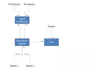
Explore why a multi-cycle approach is chosen over single-cycle or pipelined designs for CPU hardware, emphasizing hardware reuse and ease of implementation. Learn about instruction formats, data flow, and steps in a multi-cycle implementation.

E N D
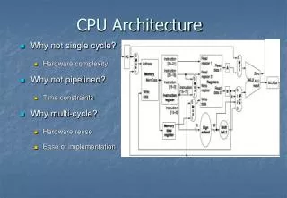
CPU Architecture • Why not single cycle? • Hardware complexity • Why not pipelined? • Time constraints • Why multi-cycle? • Hardware reuse • Ease of implementation
Instruction Formats R I J • Formats: • Address fields are not 32 bits — How do we handle this with load and store instructions?
Idea behind multicycle approach • We define each instruction from the ISA perspective • Break it down into steps following our rule that data flows through at most one major functional unit (e.g., balance work across steps) • Introduce new registers as needed (e.g, A, B, ALUOut, MDR, etc.) • Finally try and pack as much work into each step (avoid unnecessary cycles)while also trying to share steps where possible (minimizes control, helps to simplify solution) • Result: Our multi-cycle Implementation!
Five Execution Steps • Instruction Fetch • Instruction Decode and Register Fetch • Execution, Memory Address Computation, or Branch Completion • Memory Access or R-type instruction completion • Write-back stepINSTRUCTIONS TAKE FROM 3 - 5 CYCLES!
Step 1: Instruction Fetch • Use PC to get instruction and put it in the Instruction Register. • Increment the PC by 4 and put the result back in the PC. • Can be described succinctly using RTL "Register-Transfer Language" IR <= Memory[PC]; PC <= PC + 4; • What is the advantage of updating the PC now?
Step 2: Instruction Decode and Register Fetch • Read registers rs and rt in case we need them • Compute the branch address in case the instruction is a branch • RTL:A <= Reg[IR[25:21]];B <= Reg[IR[20:16]];ALUOut <= PC + (sign-extend(IR[15:0]) << 2); • We aren't setting any control lines based on the instruction type (we are busy "decoding" it in our control logic)
Step 3 (instruction dependent) • ALU is performing one of three functions, based on instruction type • Memory Reference: ALUOut <= A + sign-extend(IR[15:0]); • R-type: ALUOut <= A op B; • Branch: if (A==B) PC <= ALUOut;
Step 4 (R-type or memory-access) • Loads and stores access memory MDR <= Memory[ALUOut]; or Memory[ALUOut] <= B; • R-type instructions finish Reg[IR[15:11]] <= ALUOut;The write actually takes place at the end of the cycle on the edge
Step 5 (Write-back step) • Reg[IR[20:16]] <= MDR;
Complete Multi-Cycle Datapath Text – Fig. 5.28