Download
1 / 24
300 likes | 527 Views
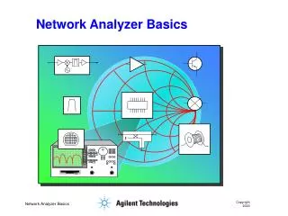
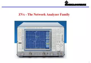
Network Analyzer Operation. 2004 ITTC Summer Lecture Series. John Paden. Purposes of a Network Analyzer. Network analyzers are not about computer networks! . Purposes of a Network Analyzer. Measures S-parameters of electronic devices.

E N D
Network Analyzer Operation 2004 ITTC Summer Lecture Series John Paden
Purposes of a Network Analyzer • Network analyzers are not about computer networks!
Purposes of a Network Analyzer • Measures S-parameters of electronic devices. • E.g. Filters, amplifiers, mixers, switches, antennas, etc. • S-parameters are complex numbers (i.e. amplitude and phase) • S-parameters are a generalization of the idea of the transfer function. • Remember transfer functions from EECS 360 (signal analysis course) • The transfer function of a device does not include information about the input and output impedance of a device. Therefore it does not tell you how the device will behave when connected to other components. • Network analyzers are similar to continuous wave (CW) radar systems • These two systems share many features.
Terminology • The device or system to be tested is referred to as the DUT or Device Under Test. • The test fixture refers to the system outside of the network analyzer that is connected to the DUT. • While the test fixture is part of what the network analyzer measures, we ultimately want to measure the DUT by itself. • Most of the time, the test fixture is just a pair of cables used to connect the network analyzer to the device. • LTIV stands for Linear Time-Invariant.
Overview of NA Operation • The network analyzer measures in the frequency domain. • The network analyzer transmits a sinusoid into the test fixture with a known frequency, amplitude, and phase. • The network receives the amplitude and phase of one frequency from the output of the test fixture. • The transmitted and received sinusoids do not have to be the same frequency. • For most measurements the frequencies are the same.
Linear Time-Invariant Devices • A device is called LTIV if its operation can be explained by convolution. • This means that the output signal is based on a infinite summation of scaled and time-delayed versions of the input signal. • The coefficients in this infinite summation never change. • Now think about what happens when you have an infinite summation of scaled and time-delayed version of a single sinusoid. • After all the summations you will end up with a sinusoid of the same frequency. Its phase and amplitude (which completely characterize it) are determined by the summations.
Network Analyzer Operation * Incident, reflected, and transmitted fields are sinusoids
Taking a Measurement: Start/Stop Freq • Decide at which frequencies you want to know how your device performs. • Set your network analyzer’s start and stop frequencies. If you plan to time-gate or process the data add some guard room on each side (i.e. make your start frequency a little lower and your stop frequency a little higher). • PRISM SAR example: We have a Low Pass Filter (LPF) with a cutoff frequency of 90 MHz. We want to know what its passband behavior is and its stopband behavior at 450 to 470 MHz where the GPS telemetry radio link operates. • We will want to measure the device from near DC up to 500 MHz. • Suggest using HP 8753D (300 kHz-6 GHz) • start frequency: 300 kHz • stop frequency: 500 MHz
Taking a Measurement: # of points • Determine the maximum length of the impulse response. • PRISM SAR example: Continuing are LPF example, let us assume that we have a total of 2 meters of cable with a velocity factor of 69.5% and the LPF has four sections. We want to include up to 10 reflections through the system. • Total time:
Taking a measurement: # of points • We know the bandwidth (BW) of our measurement: • BW = stop frequency – start frequency = 500 MHz • We know the maximum length of the impulse response that we are interested in: 511 ns • We can now calculate the number of points in the frequency domain we must sample at:
Taking a measurement: Transmit Power • We want to measure the stopband attenuation down to –90 dB with 16 dB SNR. • Our low pass filter is high-power so we can transmit at the highest power the network analyzer provides: 10 dBm transmit power. • The signal power with 90 dB of attenuation is then -80 dBm. To achieve the desired 16 dB SNR, the noise floor must be –96 dBm. • Using a noise figure of 53 dB for the network analyzer, the input noise power is: K = Boltzmann’s Constant (1.38e-23) T = IEEE ref. Temp. (290 K) B = receiver bandwidth F = Receiver noise figure (53 dB)
Taking a Measurement: IF Bandwidth • To achieve an SNR of 16 dB, we need to set our receiver bandwidth so that 10Log10(B) is 25 dB or less. Therefore B needs to be 300 Hz. • The network analyzer calls receiver bandwidth “IF bandwidth” where IF stands for intermediate frequency.
Taking a Measurement: Averages • Suppose we wanted to use an IF bandwidth of 10000 Hz (now 10Log10(B) = 40 dB). • Another way to increase the SNR to the appropriate level would be to average 40 measurements. This effectively uses forty times the energy (similar to increasing the power by 16 dB). • The whole equation becomes:where P = transmit power in Watts, N = number of averages, and L = loss of DUT.
Taking a Measurement: Sweep Time • In Sweep Mode (as opposed to stepped mode), the network analyzer transmits a linear chirp in sweep mode.
Taking a Measurement: Sweep Time • Sweep Time: The time it takes the network analyzer to measure all of its frequencies. • IF Bandwidth • ImpulseResponse Delay
Taking a Measurement: Sweep Time • Solution: Increase Sweep Time
Taking a Measurement: Sweep Time • Closer Look: We have set our network analyzer to 401 points. At each point, the network analyzer waits 1/300 seconds (that is the typical group delay through a filter with a bandwidth of 300 Hz). • The impulse response is 511 ns long at most. Therefore the sweep rate is: • The change in frequency during the impulse response is:
Taking a Measurement: Sweep Time • The sweep time is always okay if you are properly sampling the frequency domain!
References • Ballo, David, Network Analyzer Basics, Back-to-Basics Seminar, Hewlett-Packard Company, 1997. • HP 8753D User Guide, Hewlett-Packard Company. • HP 8720 User Guide, Hewlett-Packard Company.
Example • PRISM SAR example: We want to measure our antennas. • There is a total of 100 meters of cable, all with a velocity factor of 75%. • The separation between the two antennas is 30 meters and the longest multipath expected is 80 meters. • The frequencies of interest are 50-500 MHz. • The antennas will receive noise power from radio stations (GIVE LEVEL HERE). • The 1 dB compression point of the transmit amplifier is 25 dBm and it has 35 dB of gain.
Example • Determine start and stop frequency • Determine transmit power • Determine number of points • Determine IF bandwidth and averaging • Calibrate network analyzer • Save calibration • Take measurements
DUT Example • Filters • The local Sunflower cable network uses approximately 1 GHz of bandwidth on their cable network. • Each channel occupies 5.5 MHz of this bandwidth. • Sunflower offers several options: basic, unlimited, data, etc. • The channels that come with the basic package are grouped into the lower part of the spectrum. Therefore, subscribers to the basic service have a low pass filter placed on the cable into their house. • The channels used for data are grouped in the upper part of the spectrum. These subscribers have a high pass filter placed on the cable into their house.