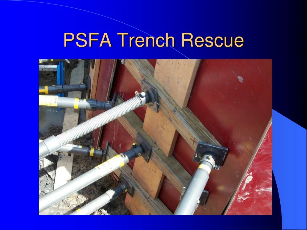
PSFA Trench Rescue
710 likes | 1.04k Views
Learn the essential OSHA guidelines, identify trenching hazards, soil composition impact, victim survival strategies, and trench rescue techniques. Comprehensive safety reference material.

PSFA Trench Rescue
E N D
Presentation Transcript
Relevant Reference Material OSHA 29 CFR1926.650: Scope, Application and Definitions OSHA 29 CFR1926.651: Specific Excavation Requirements OSHA 29 CFR1926.652: Requirements for Protective Systems OSHA 29 CFR 1926 Subpart B Appendices A-F National Fire and Rescue; Trench Rescue Secrets, Parts 1 & 2. Patrick Moore FEMA Structural Collapse Technician Course, Student Manual, Module 2B Shoring Construction, http://www.fema.gov/emergency/usr/sctc.shtm
Introduction Each year, 1,100 workers are severely injured and 100 workers die in trenching and excavating accidents
Why do trench accidents occur?? • Complacency • Shortcutting of safety for profit • Weekend warriors-no shoring utilized • Ignorance of hazards • Unprepared or poorly trained in excavation
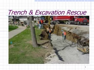
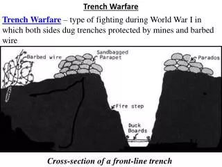
Anatomy of a Trench • Trench-Trenches are narrow excavations made below the surface of the ground. In general, the depth is greater than the width. However, the width of a trench is not greater than 15 feet. An excavation is also considered to be a trench • In reality, an open grave waiting for an occupant
Inherent trench problems Natural and man made forces began acting immediately to close a trench once its been created These forces overcome the strength of the soil composition and cause the trench to eventually collapse
Dirt Dynamics • 1 cubic foot of dirt weighs 100 lbs • 1 cubic yard of dirt weighs 2,700-3,500 lbs • 1 cubic foot of dirt will fill eight 1 gallon buckets • 1 cubic yard of dirt will fill 203 1 gallon buckets 3 1 1 3 3 1 3
Soil Types • Type A-Most stable:clay, silty clay and hardpan (resists penetration) No soil is type A if it is fissured, is subject to vibration of any type, has previously been disturbed or has seeping water • Type B-Medium stability:silt, sandy loam, medium clay and unstable dry rock, previously disturbed soils unless otherwise classified as Type C. Soils that meet the requirements of Type A soil but are fissured or subject to vibration
Soil Types continued: • Type C-Least stable:gravel, loamy sand, soft clay, submerged soil or dense, heavy unstable rock and soil from which water is seeping freely
Soil Effects on Victim • Traumatic Asphyxiation • Soil restricts expansion of victims chest • Soil blocks airways • Causes suffocation • Impact crushes the victim: • Breaking limbs • Causing internal injuries • Causing soft tissue injuries
Victim Survival Profile • Time is the biggest factor • 8-10 min.’s for response • 6-10 min.’s for initial assessment • 18” of dirt = 2500-3500 pounds • Hazard Risk Assessment Profile needs to be considered
Types of Trench Accidents Spoil pile slide Occurs when improper techniques are used and the excavated material is not placed far enough away from the trench lip UNSAFE
Slough In (cave in) Slough trench lip Most commonly occurs to previously excavated materials, primarily in sand, gravel mixtures
Side wall shear Occurs commonly to clay type soils exposed to drying Side wall shear
Trench Terminology Lip extends 2 feet vertically and horizontally from the edge of the trench. If the spoil pile is located within 2 feet of the trench, it must be removed. Lip
Padding the Lip Acceptable materials: 2 x 12 lumber, 4 x 8 ¾” or 5/8” plywood or trench panels. Should extend from an area of stability to instability, if end of trench is accessible, start there.
Trench Terms Angle of Repose The greatest angle above the horizontal plain at which loose soil will lie without sliding. Reducing this angle will reduce the amount of spoil slide
Trench Terms Uprights-Vertical supports that attach panel to upright. Shoring is attached to uprights between panels (usually 2 x 8’s or 12’s) Panels-Support side walls of trench Pre-made Shore form panels, 4 x 8 sheeting of 2 ¾” plywood Shoring-Horizontal bracing between panels, can be pneumatic or timber shoring
Terms Scabs-Hold timber shoring firmly in place against uprights. 2 x 4 pieces Spoil pile-The material excavated from the trench
TrenchTerms Lowering lines-Line used to lower pneumatic shoring. Lines should be of a different color
Making the Trench Safe • Three ways to “safe” a trench: • 1.-Slope the angle of repose • 2.-Benching • 3.-Shoring/Shielding Sloping the angle of repose and benching require backhoes as well as additional manpower. Shoring operations require well trained coordinated rescuers
Shoring Basics Shoring Types:Shoring is the provision of a support system for trench faces used to prevent movement of soil, underground utilities, roadways and foundations.
Shoring Types Hydraulic Shoring: A prefabricated strut and/or system manufactured of aluminum or steel. Pressurized w/5 gal hand pump to 500-1000 psi. Pressure must be maintained, no locking device.
Shoring Types Pneumatic Shoring System: Works in a manner similar to hydraulic shoring, primary difference is that pneumatic shoring uses air pressure to set shores (can be set manually) Pneumatic Strut Swivel strut base Strut Extension
Shoring Types Timbering: Difficult and time consuming task. 4 x 4 lumber generally used for timbering.
Shoring Objective Transfer the force across the trench through the upright and then into the opposite trench wall. Transferring the potential energy will complete the protective system giving rescuers a safe area in which to work
Shielding Trench boxes are different from shoring because instead of shoring up the trench face, they are intended to primarily protect workers from slough ins.
Shoring Operations • Shores should be located 18”-24” from the floor and the lip of the trench • Shores should be no more than 48” apart vertically • Placement of the first shore should be from the outside of the trench using hydraulic/pneumatic shoring (shores should not be placed directly above the pt/victim)
Pneumatic Shoring Order • First shore should be placed in the middle of the upright • Second shore is placed in the top of the upright • Third shore is paced in the bottom of the upright • shores are lowered by lowering lines directed by the shoring officer then “shot”
Shooting Shores • After shore is lowered and is in place (level), the following commands are to be given by shoring officer: • “Prepare to Shoot” • “Shoot” • Pneumatic shores are shot at 100 psi and released at 150 psi
Corner Shoring Force Block 6 x 6
Nailing Shores Nail half way into 45 swivel base and then bend nail over corner of base
Wales Horizontal members, installed on either the inside or outside of panels, to span openings along the trench walls or create a space by spanning panels. Inside Wale
Wales Outside Wale: To span a slough in of a trench wall. Note the Low pressure bag
Timbering • The first shore is placed at the top of the upright and requires the rescuer to enter the trench on a ladder • The second shore or middle shore is placed in the middle of the upright, again forcing rescuer further in the trench on a ladder • Last shore is placed on the bottom of the trench above trench floor
Railing the Uprights 2” x 4” are nailed onto the uprights Scab blocks then inserted to hold timer above/below Faster and easier than traditional scab block method
Alternate Railing Method 2” x 4”’s placed horizontally above and below timbers Railing nailed on in the same fashion, allow for timer to slide vertically (scab block width)
Hazards may include: Electrical utilities Ruptured gas lines Broken water/sewer lines Workers on scene Spoil pile Falling debris in trench O2 deficient atmosphere Vibration from: Operating machinery on scene Nearby traffic Responding apparatus Hazard Control
Rescue Operations DO NOT GO INTO THE HOLE!!!! First and foremost, the company officer needs to limit the possibility of further injuries and death, get the hole under control, make it safe for everyone, and, with the proper equipment, start to develop a safe work space.
Safety First • Appropriate PPE: • Dress for success, right gear should include head, hand, foot, eye, ear and respiratory protection as appropriate. • Make the general area safe: • Establish a hot, warm and cold zone
Safe the General Area • First arriving apparatus: • Stops and is turned off no less than 250’ from the dispatched location. This becomes the warm zone • Establish command and designate a staging area for other other responders with equipment/apparatus. • Assign a staging officer
Cold/Hot Zone • Cold Zone Staging should exceed 500’or more from trench incident site • Hot Zone Area: • Should extend 100’ in all directions around the site • Use fire line tape, rope, etc. to mark these zones
Rehab Operations PIO Trench Staging 100 Feet Personnel Staging IC 250 Feet 500 Feet
Outer Circle Check • Restrict entry to site • Eliminate sources of vibration, stop and shut down construction equipment • Identify witnesses to the accident if any • Identify job foreman • Begin to establish incident perimeters
Inner Circle Check • Approach site from end of trench • Identify victim location (if possible) using witnesses, location of trench failure, surveyors markers etc. • Identify number of patients • Establish patient/victim condition if possible