Download

1 / 65
670 likes | 959 Views
POLITECNICO DI BARI. DIMeG & CEMeC Via Re David 200, 70125, Bari, ITALY. Wall modeling challenges for the immersed boundary method. G. Pascazio. pascazio@poliba.it. M. D. de Tullio , P. De Palma, M. Napolitano; G. Iaccarino, R. Verzicco; G. Adriani, P. Decuzzi …….

E N D
POLITECNICO DI BARI DIMeG & CEMeC Via Re David 200, 70125, Bari, ITALY Wall modeling challenges for the immersed boundary method G. Pascazio pascazio@poliba.it M. D. de Tullio, P. De Palma, M. Napolitano; G. Iaccarino, R. Verzicco; G. Adriani, P. Decuzzi ……. Workshop Num. Methods non-body fitted grids - Maratea, May 13-15 2010
OUTLINE • Immersed Boundary technique • Tagging, Forcing, Near-wall reconstruction • High-Re turbulent flows: wall modeling • Tables, Analytical, Numerical • Preconditioned compressible-flow solver • Results • Arbitrarily shaped particle transport in an incompressible flow • Fluid-structure interaction solver • Results
TAGGING Cartesian Grid Geometry “fluid” cells “ray tracing” “solid” cells interface cells A special treatment is needed for the cells close to the immersed boundary
FORCING During the computation, the flow variables at the center of the fluid cells are the unknowns, the solid cells do not influence the flow field at all, and at the interface cells the forcing is applied • Direct forcing(Mohd-Yusof) • - The governing equations are not modified • - The boundary conditions are enforced directly • Sharp interface The boundary condition has to be imposed at the interface cells, which do not coincide with the body. Thus, a local reconstruction of the solution close to the immersed boundary is needed.
Locally refined grids: automatic generation Procedure (de Tullio et al., JCP 2007) Generation of a first uniform mesh (Input: Ximin , Ximax , DXi ) Refinement of prescribed selected regions( Input: Ximin , Ximax , DXi ) Automatic refinement along the immersed surface( Input: Dn, Dt) Iterative Automatic refinement along prescribed surface( Input: Dn, Dt ) Iterative Coarsening
One-dimensional approach (Fadlun et al., JCP 2000) At each interface cell, a linear interpolation is employed along the Cartesian direction closest to the normal to the immersed surface RECONSTRUCTION
RECONSTRUCTION Multi-dimensional linear recontruction (2D) (e.g., Yang and Balaras, JCP 2006) Dirichlet boundary condition: Neumann bounary condition:
DISTANCE-WEIGHTED RECONSTRUCTION (LIN) (de Tullio et al., JCP 2007) Dirichlet boundary conditions: Neumann boundary conditions:
NUMERICAL METHOD • Reynolds Averaged Navier-Stokes equations (RANS) • k-ω turbulence model (Wilcox, 1998): • Pseudo-time derivative term added to the LHS to use a “time marching” approach for steady and unsteady problems (Venkateswaran and Merkle, 1995) • Preconditioning matrix Γto improve the efficiency for a wide range of the Mach number (Merkle, 1995) • Euler implicitscheme discretization in the pseudo-time • 2nd order accurate three point backward discretization in the physical time • Diagonalization procedure (Pulliam and Chausee, 1981) • Factorization of the LHS
NUMERICAL METHOD • BiCGStab solver to solve the three sparse matrices: • Colocated cell-centred finite-volume space discretization • Convective terms: 1st, 2nd and 3rd order accurate flux difference splitting scheme or 2nd order accurate centred scheme • Viscous terms: 2nd order accurate centred scheme • Minmod limiter in presence of shocks • Semi-structured Cartesian grids
MESH-REFINEMENT STUDY • NACA-0012 • M=0.8, Re=20, angle of attack= 10° • Space domain: [-10 c , 11 c] [ -10 c , 10 c] • 5 meshes: • “Exact” solution obtained by means of a Richardson extrapolation employing the two finest meshes:
MESH-REFINEMENT STUDY pressure velocity, u component temperature velocity, v component
Heated circular cylinder • M=0.03; Re=100,120,140; T*=1.0, 1.1, 1.5, 1.8 (T* = Tw/Tinf) • (-10,40) D – (-15, 15) D • - Mesh: 41509 cells, 293647 faces • - T (Energy equation) is crucial for T*>1 • unsteady periodic flow Temperature contours (Re=100, T*=1.8) Exp: (Wang et al., Phys. Fluids, 2000)
Supersonic flow past a cylinder Flusso supersonico su cilindro • M=1.7; Re=2.e5 • Domain: (-10,15) D – (-10, 10) D Locally refined mesh: 75556 cells 545700 faces q =113° q =112° (exp.) CD= 1.41 CD= 1.43 (exp.) Mach number contours Pressure coefficient
Cross-flow oscillating cylinder - Re=500, M=0.003 Imposed cross-flow frequency Natural shedding frequency (fixed cylinder) α(t)=y(t)/D vorticity (F=0.875) Ref.[1]: Blackburn, J.Fluid Mech, 1999
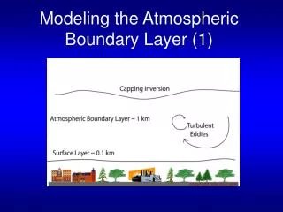
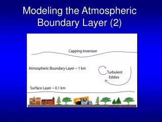
logarithmic layer: viscous sublayer: WALL MODELING • Linear interpolation is adequate for laminar flows or when the interface point is within the viscous sublayer • Brute-force grid refinement is not efficient in a Cartesian grid framework • Local grid refinement alleviates the resolution requirements, but still it is not an adequate solution for very high Reynolds number flows Wall functions: motivated by the universal nature of the flat plate boundary layer
WALL FUNCTIONS • The Navier Stokes equations are solved down to the fluid point P1 • Flow variables at the interface point I are imposed solving a two-point boundary value problem: P1 F1 I Turbulence model equations W
WALL FUNCTIONS (TAB) (Kalitzin et al. J. Comput. Phys. 2005) It is possible to define a local Reynolds number, based on y and U. The following is a universal function: This function is evaluatedonce and for allusing a wall resolved, grid-converged numerical solution and stored in a tablealong with its inverse (look-up tables)
WALL FUNCTIONS (TAB) Compute velocity in F1 Compute friction velocity corresponding to IB surface (W), based on wall model uF1 , yF1 , nF1 ReF1 ReF1,[tables] y+F1 ut = (y+F1 nF1) / yF1 F1 Extract mean velocity and turbulence quantities in I I W ut , yI , nI y+I y+I ,[tables]u+i , k+i, w+i ut , yI , u+i , k+i, w+i ui , ki, wi F1-W is equal to twice the largest distance from the wall of the interface cells
WALL FUNCTIONS (ANALYTICAL) (Craft et al. Int. J. of Heat Fluid Flow, 2002) To simplify integration, rather than a conventional damping function, a shift of the turbulent flow origin from the wall to the edge of the viscous layer is modeled. Molecular and turbulent viscosity variations: where: viscous sublayer (variation of fluid properties in the viscous sublayer is neglected)
WALL FUNCTIONS (ANALYTICAL) (Craft et al. Int. J. of Heat Fluid Flow, 2002) Velocity variation in the near-wall region: The equation is integrated separately across the viscous and fully turbulent regions, resulting in analytical formulations for U, given the value of UN : Shear stress:
TWO-LAYER WALL MODELING Point F1 is found, along the normal-to-the-wall direction, at twice the largest distance from the wall of the interface cells A virtual refined mesh is embedded between the wall point W and F1 in the normal direction P1 • The Navier Stokes equations are solved down to the fluid point P1 F1 • Velocity at F1 is interpolated using the surrounding cells h • Simplified turbulent boundary layer equations are solved at the virtual grid points I • Velocity at the interface point I is interpolated W
WALL FUNCTIONS (NUMERICAL, NWF) Momentum equation (Balaras et al. 1996; Wang and Moin, 2002) : y = normal direction x = tangential direction The eddy viscosity is obtained from a simple mixing length model with near wall damping (Cabot and Moin, FTC 1999) : k = 0.4 A=16 An iterative procedure has been implemented to solve the equations simultaneously • Boundary conditions: • velocity at point F1 (interpolated from neighbours fluid nodes) • velocity at the wall (zero).
WALL FUNCTIONS (THIN BOUNDARY LAYER, TBLE) Momentum equation: y = normal direction x = tangential direction Turbulence model equations: An iterative procedure has been implemented to solve the equations simultaneously • Boundary conditions: • at point F1 (interpolated from neighbours fluid nodes) • at the wall (zero velocity and k, and Menter for w).
FLAT PLATE • n = 1.6 x 10⁻⁵ m2/s • Uinf = 90 m/s • ReL=1 = 6 x 10⁶
RECIRCULATING FLOW • ReL = 3.6 x 10⁷ • L = 6 m • A = 0.35 x Uinf • Uinf= 90 m/s x/L = 0.16 x/L = 0.58 x/L = 0.75
RECIRCULATING FLOW x/L = 0.16 x/L = 0.58 x/L = 0.75
VKI-LS59 Turbine cascade M2,is= 0.81, 1.0, 1.1, 1.2 Re = 8.22x10⁵, 7.44x10⁵, 7.00x10⁵, 6.63x10⁵ • Locally refined mesh: 33301 cells • wall functions (Tables) M2,is=1.2 M2,is=1.2 Mis along the blade Mach number contours
RAE-2822 AIRFOIL Wall resolved reference solution: 700000 cells. IB grid: 20000 cells; Local view of the grid Local view of the grid
RAE-2822 AIRFOIL Pressure coefficient distribution Mach number contours (NWF)
Conjugate heat transfer: T106 LP turbine Temperature contours
CONCLUSIONS (1) High Reynolds number turbulent flows • Wall modelling appears to be an efficient tool for computation of high-Re flows; • Different approaches have been investigated to model the flow behaviour normal to the wall: (a) look-up tables; (b) analytical wall functions; (c) numerical wall functions (NWF & TBLE); • Wall functions provide good results for attached flows; • Encouraging results for separated flows; in particular NWF and TBLE with embedded one-dimensional grids Work in progress and future developments • Study the influence of source terms • Investigate in details the robustness and efficiency issues • Include an accurate thermal wall model
Arbitrarily shaped particle transport in an incompressible flow
MOTIVATION and BACKGROUND ligands Use of micro/nano-particles for drug delivery and imaging. Properly designed micro/nano-particles, once administered at the systemic level and transported by the blood flow along the circulatory system, are expected to improve the efficiency of molecule-based therapy and imaging by increasing the mass fraction of therapeutic molecules and tracers that are able to reach their targets PEG Ferrari, Nat Can Rev, 2005
MOTIVATION and BACKGROUND ligands Particles are transported by the blood flow and interact specifically (ligand-receptor bonds) and non-specifically (e.g., van der Waals, electrostatic interactions) with the blood vessel walls, seeking for their target (diseased endothelium). The intravascular “journey” of the particle can be broken down into two events: margination dynamics and firm adhesion. PEG Ferrari, Nat Can Rev, 2005
MOTIVATION and BACKGROUND The margination is a well-known term in physiology conventionally used to describe the lateral drift of leukocytes and platelets from the core blood vessel towards the endothelial walls. The observation of inhomogeneous radial distributions of particles in tube flow dates from the work of Poiseuille (1836) who was mainly concerned by the flow of blood and the behavior of the red and white corpuscles it carries. Experimental results (Segré & Silberberg, JFM 1962) show the radial migration develops in a pipe from a uniform concentration at the entrance. Equilibrium position r/R = 0.62
MOTIVATION and BACKGROUND Matas, Morris, Guazzelli, 2004 Experimental distribution of particle position (particle diameter 900 μm) over a cross section of the flow observed for two values of the Reynolds number: Re = 60 (left) and Re = 350 (right).
Micro/nano-particle with different • size:from few tens of nm to few μm • composition: gold- and iron-oxide, silicon • shape:spherical, conical, discoidal, …. • surface physico-chemical properties: charge, ligants
Design parameters • Particle size and shape • Reynolds number based on the channel diameter • Particle density (particle-fluid density ratio) • Number of particles in the bolus • An accurate model predicting the behavior of intravascularly injectable particles can lead to a dramatic reduction of the “bench-to-bed” time for the development of innovative MNP-based therapeutic and imaging agents.
Governing equations Navier-Stokes equations for a 3D unsteady incompressible flow solved on a Cartesian grid: Rigid body dynamic equations:
Flow solver (Verzicco, Orlandi, J. Comput. Phys., 1996) • staggered-grid • second-order-accurate space discretization • fractional-step method: • non-linear terms: explicit Adam-Bashford scheme • linear terms: implicit Crank-Nicholson scheme • immersed boundary with 1D reconstruction • (Fadlun et al., J. Comput. Phys., 2000)