Download
1 / 31
310 likes | 507 Views
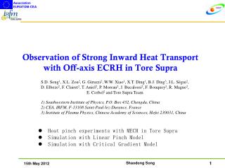
TORE SUPRA. TORE SUPRA. Integration of High Power, Long Pulse Operation in Tore Supra in preparation of ITER. M. Chatelier, on behalf of Equipe Tore Supra. LHCD Power (MW). Transformer flux (Wb). T e (0) (keV). Line averaged density (x10 19 m -2 ). T i (0) (keV). Neutron (x10 10 /s).

E N D
TORE SUPRA TORE SUPRA Integration of High Power, Long Pulse Operation in Tore Supra in preparation of ITER M. Chatelier, on behalf of Equipe Tore Supra
LHCD Power (MW) Transformer flux (Wb) Te(0) (keV) Line averaged density (x1019m-2) Ti(0) (keV) Neutron (x1010/s) Zeff Tore Supra, large superconducting tokamak devoted to long-duration, high performance discharges • 3rd largest tokamak • Operation of the cryo-magnetic system for 18 years • All PFCs actively cooled • 6 min discharges (2003) with 1 GJ injected/exhausted energy • PLHCD = 3 MW • Ip = 0.5 MA • ne0 = 2.5 1019m-3
Injected power 9.5 MW Large margin towards higher power long discharges • Convective losses routinely handled by the TPL (3-5 MWm-2) • H/CD systems initially designed for 30 sec operation; ongoing upgrade (seeBeaumont et al., IT/2-5) • towards 10-12 MW for 1000 sec, near Greenwald • Tore Supra current program: • Investigation NI discharges • Preparation scenarios & techniques for high power long pulse operation (based on LHCD & ICRH)
Tore Supra CIMES project (2008, continous Current drive) CIEL project (2003, active cooling)
Outline • Safely operating Tore Supra at multi-MW level • Multi-MW long duration discharges results • Integrating operational controls for steady-state scenarios • Turbulence measurements and local transport analysis • Plasma wall interaction during long discharge operation • Technological developments for long discharge operation follow-up • Conclusions and prospects
10 MW in TS representative of ITER operation in term of averaged power density & heat exhaust
LHCD launcher A: fast electrons B: fast ion direct losses C: Arcing ICRH antenna A: fast electrons B: fast ion direct losses C: Rectified sheath (see Goniche et al. EX/P6-12) A (1000°) C (800°) C A(800°) A(800°) B (800°) B(600°) B’ (1000°) Handling localized heat loads
LHCD launcher zone B LHCD launcher zone A Safely operating Tore Supra at 10 MW level • 20 areas monitored delivering Real Time IR signals • Each used in RT controller with specific safety strategy
Significant ion heating at high Greenwald fraction • Ip = 0.9 MA; ne0 = 5 1019 m-3; 8.4 MW H/D minority • Ti close to Te • HITER-L = 1.3 #33612
Toroidal rotation observed with ICRH • Suggests sheared rotation • Could explain confinement improvement through ITG and TE modes stabilization (Kinezero)
#33898 Ptot PICH = 6.3 MW PLH = 3.1 MW Greenwald fract. = 0.93 bN = 0.83 q(0) non-inductive fract. ~ 50% Long sawteeth-free discharges with ICRH & LHCD • Ip = 0.6 MA; ne0 = 4 1019 m-3; q(0) above 1 • Reminiscent of hybrid scenarios, but q profile controlled by LHCD
Optimising plasma performance reliability #36133 • Fully NI long discharges prone to MHD activity • Small MHD free operating window (see Maget et al. EX/P8-21) • RT current profile control: • Actuator LHCD n// • Sensor HXR width • Combined with control of: • Ip (LHCD power) • Flux consumption (primary) • Triple control at low loop voltage (< 10 mV) (see Joffrin et al., EX/1-6)
Integrating plasma optimisation and safe operation • RT IR safety + triple control • Discharges 70 sec / 7MW controlled in MHD free window • Pioneers integration work for ITER when combining: • global performance • profile shaping • plasma stability • PFCs protection
Neoclassical level pinch observed inside q=1 in plasma • Progressive density build-up during sawtooth recovery • Inward pinch 0.1 ms-1 Ware pinch • Low diffusion 0.1 ms-2 coherent with low ñ level • Vanishes with high CD and/or heating power see Hennequin et al., EX/P4-36
Supported by density fluctuation measurements scaling experiments in L mode • Two sets of discharges n= 0.5 / BT= 3.8T & n= 0.2 / BT= 3.2T with matched *, * & q profiles • Weak degradation. exponent: • Global confinement -0.2 0.15 • Effective diffusivity -0.2 0.4 • ITER L-mode scaling -1.4 • Supported by density fluctuation measurements • Bias in extraction of dimensionless scaling law extraction?
Plasma wall interaction issues during long discharge operation
D retention rate (D/s) D/C = 0.1 Time (s) Fuel retention in Carbon walls • Long term constant retention rate observed (50-80% injected flux) • Repetitive behaviour on 3 consecutive shots (15 min)
D retention rate (D/s) D/C = 0.1 Time (s) Bulk diffusion, a credible retention mechanism • Evidenced in laboratory experiments at high fluence (fl) • Key parameter: exposure time • Retained fraction (fluence)0.5 • Simple model: implantation up to saturation + evolution retained fraction (fluence)0.5 • Needs to be refined • Extrapolation to ITER: • Bulk diff. possible, but fl0.5 • Codeposition (fl) still major concern • Detritiation difficult for both
Flows in the SOL: a common physics for divertor and limiter machine • Half recycling at each strike zone + uniform radial outflux from core => nearly stagnant flow at Mach probe
Evidence of strong outflux across the outboard midplane • Large SOL width when unobstructed by outboard limiter • SOL fed by long range parallel bursty transport events located near the outboard midplane (see Gunn et al., EX/P4-9)
Technological developments for long discharge operation follow-up
Articulated Inspection Arm operational in 2007 • In vessel remote handling light payload carrier (10kg) • able to reach all part of TS chamber without breaking vacuum • 8-meter long, 5 modules with 2 actuated joints each • Prototype module tested under ITER representative vacuum and temperature condition • Various use: • High definition CCD for inspection • Leak testing tool • Laser ablation tool for surface characterization and codeposited layer removal (see Semerok et al., IT/P1-15)….
Conclusions and … • After 3MW/LH 6mn discharges of 2003, Tore Supra has performed high power long pulse discharges (5-10MW, 20-60s) still far from the limits of the actively cooled pump limiter • Substantial progress in real time control of safe HF -non inductively driven and heated - discharges: • Minority ICRH & LH driven steady state discharges • Real time control of antennas temperature • Real time control of current profile • Extensive density fluctuation measurements bring coherence in transport and stability studies • Large and continuous D absorption by the C wall suggesting large bulk diffusion process at work • Edge particle radial transport primarily on the outboard side consistently with Langmuir probe measurements
… Prospects • Enhancement of the LH power & duration in preparation (CIMES project: 6-8MW, 1000s) • Steady state high power non inductive real time controlled discharges • Physics of non inductive discharges • Preparation of articulated inspection arm for several purposes • Visual inspection of PFCs • Vacuum leak test • D recovery … under real conditions of temperature/vacuum • Pursue building experience in integrating ITER relevant constraints for high power operation in actively cooled environment Complementary of JET (& ASDEX-U) with all metal wall and high NBI
Monday 16th • E. Joffrin et al., EX/1-6 • Tuesday 17th • Semerok et al., IT/P1-15 • Garbet et al., TH2-2, Beyond scale separation in gyrokinetic turbulence • Bécoulet M. et al., IT/P1-29, Modelling of edge control by ergodic fields in DIII-D, JET and ITER • Wednesday 18th • Durocher et al., FT/1-5 • Thursday 19th • Hogan et al., EX/P4-8, Mechanisms for carbon migration and deuterium retention in Tore Supra CIEL long discharges • Gunn et al., EX/P4-9 • Hennequin et al., EX/P4-36 • Friday 20th • Goniche et al. EX/P6-12 • Saturday 21th • Libeyre et al., IT/2-1Ra, Remaining issues in superconducting magnets for ITER and associated R&D • Beaumont et al., IT/2-5 • Huysmans et al., TH/P8-2, MHD stability in X-point geometry : simulation of ELMs • Maget et al. EX/P8-21
#37421 #37193 #36970 #36854 T (°C) B4C flakes T 200°C ICRH Q5 Q1 Q2 time (s) Discriminating spurious overheated zones • High temperature measured on poorly adherent objects • Identified by follow-up of reference discharges • Spurious zones excluded from monitored area
[H. Atsumi et al., JNM 313-316 (2003)] Trapping sites Permeation through open pores Molecular “diffusion” Transient retention (Phase 1) Long term retention (long pulse / high flux)