Download
1 / 24
240 likes | 345 Views
Explore the latest developments in TOF detectors with high-resolution timing for particle identification in collider experiments. Discover the potential for kaon and charmed particle identification, plus photon-vertexing applications. Join the progress in R&D efforts for future field advancements. Witness the simulations, measurements, and innovations propelling detector technology forward.

E N D
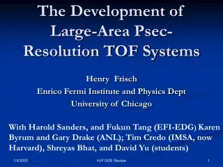
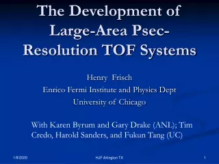
Psec-Resolution Time-of-Flight DetectorsT979 Argonne, Chicago, Fermilab, Hawaii, Saclay/IRFU, SLAC Camden Ertley University of Chicago All Experimenters Meeting July 14, 2008 (Bastille Day!)
T979 People/Institutions • Argonne National Laboratory • John Anderson, Karen Byrum, Gary Drake, Ed May • University of Chicago • Camden Ertley, Henry Frisch, Heejong Kim, Jean-Francois Genat, Andrew Kobach, Tyler Natoli, Fukun Tang, Scott Wilbur • Fermilab • Michael Albrow, Erik Ramberg, Anatoly Ronzhin, Greg Sellberg • Saclay/IRFU • Emilien Chapon, Patrick LeDu, Christophe Royon • Hawaii • Gary Varner • SLAC • Jerry Va’vra
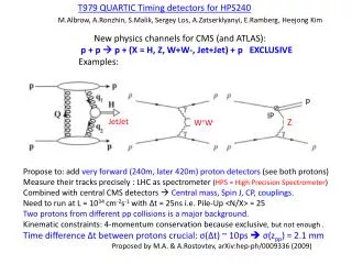
Motivation- Following the quarks • A substantial fraction of the HEP community has converged on a small number of collider experiments- Atlas, CMS, ILC • Budget > 1 billion $/year • Output is 3-vectors for most particles, plus parton type (e,mu,tau,b,c,..) for some- there is still some fundamental information we could get, and need. • Worth the investment to identify the kaons, charmed particles, b’s, …- go to 4-vectors. Nothing more left for charged particles! • Possible other application- photon-vertexing. Add converter in front- know velocity, with transit-time vertex photons. (e.g. H->gg, LHCb, K->p n n). • Serious long-term detector R&D will pay off in many fields- one example- H. Nicholson- proposed use of high-res time/pos in DUSEL water-Cherenkov full coverage. Great education for young folks too! • MTest is a key facility for the future of the field. We appreciate it!
K-Pi Separation over 1.5m Assumes perfect momentum resolution (time res is better than momentum res!) 1 Psec
Characteristics we need • Feature size <~ 300 microns • Homogeneity -ability to make uniform large-area – e.g. 30 m2 for CDF-III or ATLAS • Fast rise-time and/or constant signal shape • Lifetime (rad hard in some cases, but not all) • System cost << silicon micro-vertex system
Idea 1: Generating the signal Incoming rel. particle Custom Anode with Equal-Time Transmission Lines + Capacitative. Return A 2” x 2” MCP- actual thickness ~3/4” e.g. Burle (Photonis) 85022-with mods per our work Use Cherenkov light: fast, directional Collect charge here-differential Input to 200 GHz TDC chip
Major advance for TOF measurements: Micro-photograph of Burle 25 micron tube- Greg Sellberg (Fermilab) Development of MCP’s with 2-10 micron pores Transmission line anodes Sampling electronics
Simulation and Measurement • Have started a serious effort on simulation to optimize detectors and integrated electronics • Use laser test-stands and MTEST beam to develop and validate understanding of individual contributions- e.g. Npe, S/N, spectral response, anode to input characteristics,… • Parallel efforts in simulating sampling electronics (UC, Hawaii) and detectors (UC,Saclay,Muons.inc).
Where we are-much progress! • Using `off-the-shelf’ photo-detectors, clumsy (i.e. inductive, capacitative) anodes, electronics- , but not yet new technologies -are at ~ 5-6 psec resolution with laser bench tests. • Jerry Va’vra has answered many of the questions we had even a year ago on what limits present performance. Have (crude) models in simulation to compare test results to now • Much experience with sampling- fast scopes, Gary Varner, Saclay group, Stefan Ritt- up to 6 GHz. Simulation package developed -=>understanding the electronics issues • First test beam exposure few weeks ago… • Clock distribution at psec (local) jitter (John Anderson)
Argonne Laser Lab • Measure Dt between 2 MCP’s (i.e root2 times s); no corr for elect. • Results: 408nm • 7.5ps at ~50 photoelectrons • Results: 635nm • 18.3ps at ~50 photoelectrons
Understanding the contributing factors to 6 psec resolutions with present Burle/Photonis/Ortec setups- Jerry Vavra’s Numbers • TTS: 3.8 psec (from a TTS of 27 psec) • Cos(theta)_cherenk 3.3 psec • Pad size 0.75 psec • Electronics 3.4 psec
Fermilab Test Beam Goals • To measure the timing resolution of Jerry Va’vra’s 10μm pore MCPs with new silvered radiator. • To measure the timing resolution at known S/N and Npe with 25μm pore MCPs to compare with the ANL blue/red laser curves and simulation. • To measure the timing resolution of two SiPMs (3mm x 3mm and 1mm x 1mm). • To setup and test a DAQ system for future tests (first run). • To obtain waveforms of MCP signals with a fast sampling scope (40Gsamples/sec) to compare to simulation and DAQ
Three dark boxes (Anatoly- wonderful!) 2mm x 2mm scintillator 2 PMTs for coincidence triggering in each box. 2 MCPs or SiPMs in each box 3 DAQ systems DAQ-1 uses FERA readout for fast data collection DAQ-2 CAMAC Allows other users to quickly connect to our system Tektronix TDS6154C oscilloscope 40 Gsample/sec (total of channels) Fermilab Test Beam Setup
Fermilab Test Beam Setup • MCP 1 & 2 (dark box 1) • Photonis 85011-501 • 25 μm pore • 64 anode (4 anodes tied together and read out) • 2 mm quartz face • MCP 1 had an updated ground plane, but was very noisy. • University of Chicago’s MCPs • MCP 3 & 4 (dark box 2) • Photonis 85011-501 • 25 μm pore • 64 anode (4 anodes tied together and read out) • 2 mm quartz face • Erik Ramberg’s MCPs
SLAC & Fermilab Test Beam ResultsJ.Va’vra, SLAC, Camden Ertley (UC/ANL) SLAC tests (10 GeV electrons): Fermilab tests (120 GeV protons): Fermilab beam spot (s ~7mm + halo): SLAC Beam spot (s ~2-3mm): y x • Aim: (a) low gain to minimize aging effects at SuperB, (b) be linear in a region of Npe = 30-50. • 1-st test at SLAC: typical resolution results: ssingle detector ~23-24 ps • 2-nd test at Fermilab: typical resolution results: ssingle detector ~17-20 ps • Results are consistent with a simple model. • We have reached a Super-B goal:s~ 20ps
SiPM Fermilab Test Beam ResultsAnatoly Ronzhin, FNAL • SiPM 1 • Hamamatsu 3 x 3 mm2 • Quartz radiator 6 x 6 x 12 mm3 • 1.5mm “effective thickness” • ~10 photoelectrons • SiPM 2 • Hamamatsu 1 x 1 mm2 • Quartz radiator 6 x 6 x 6 mm3 • 0.5mm “effective thickness • ~3 photoelectrons • Obtained 70ps timing resolution • Single photoelectron timing is ~121ps for SiPM 2 • Single photoelectron timing for SiPM 1 will be measured
Fermilab Test Beam Results • Preliminary results with DAQ-1 • Obtained ~24ps with MCP 3 & 4 • Cuts on pulse height were made • 8mm total radiator • 1.9kV • Preliminary results with scope. • 8ps intrinsic timing jitter. • Obtained ~26ps with MCP 3 & 4 • 5mm total radiator • 2.0 kV Ch1: MCP3 10mV/div Ch2: MCP4 10mV/div 5ns/div σ = 26ps
Future Work • We would like to schedule future test beam runs as we have new devices and electronics ready • Same process as now- use laser test-stand for development, validation of simulation- then move to testbeam for comparison with simulation with beam. • Changes to the MCPs • 10um pore MCPs (two in hand) • Transmission-line anodes (low inductance- matched)- in hand • Reduced cathode-MCP_IN MCP_OUT-anode gaps- ordered • ALD module with integrated anode and capacitive readout- proposed (ANL-LDRD) • Changes to electronics readout • Add Ritt and/or Varner sampling readouts (interleave 10 GS) –in works • First test via SMA; then integrate chips onto boards? • Development of 40 GS CMOS sampling in IBM 8RF (0.13micron)- proposal in draft • New applications/geometries (LHC/Albrow)-proposed • Test timing between two similar SiPMs, new devices
Jerry’s #’s re-visited : Solutions to get to <several psec resolution. • TTS: 3.8 psec (from a TTS of 27 psec) MCP development- reduce TTS- smaller pores, smaller gaps, filter chromaticity, ANL atomic-deposition dynodes and anodes. • Cos(theta)_cherenk 3.3 psec Same shape- spatial distribution (e.g. strips measure it) • Pad size 0.75 psec- Transmission-line readout and shape reconstruction • Electronics 3.4 psec – fast sampling- should be able to get < 1psec (simulation)
New Anode Readout- Get time AND position from reading both ends of transmission lines 32 50 ohm transmission lines on 1.6 mm centers (Tang); attach to 1024 anode pads (Sellberg) Simulation of loaded transmission line With mock MCP pulse and anode pads (Tang)
5/11/08 Version 1.0 Psec Large-area Micro-Channel Plate Panel (MCPP)- LDRD proposal to ANL (with Mike Pellin/MSD) Front Window and Radiator Photocathode Pump Gap Low Emissivity Material High Emissivity Material `Normal’ MCP pore material Gold Anode 50 Ohm Transmission Line Rogers PC Card Capacitive Pickup to Sampling Readout
Electronics Simulation-development of multi-channel low-power cheap (CMOS) readout S/N=80 ABW= 1 GHz Synthesized MCP signal 8 bit A-to-D Jean-Francois Genat
Electronics Simulation- Samplinganalog bandwidth on input at fixed S/N and sampling/ABW ratio S/N=80 Synthesized MCP signal 8 bit A-to-D Jean-Francois Genat
Summary • Successful first run- got Jerry’s Super-B data, SiPM data, 25-micron MCP data with radiators • First look at MCP data makes it plausible that it falls on our laser teststand and simulation curves for S/N,Npe- analysis in works • Got safety, dark-boxes, cables, DAQ, Elog, great bunch of collaborators, new students, etc. in place- very good start! • Have new devices/readouts in the works- start of a program. • We’re really grateful to Fermilab and all who support the Mtest testbeam.