Download
1 / 1
10 likes | 207 Views
Development of the Mechanical Battery Dept of Mechanical & Industrial Engineering, TAMUK Faculty Mentor : Dr. Larry D Peel, P.E. Students : Javier A. Lozano, Luis Muratalla, Eli Hatfield, Gary Garcia, Richard Rivera, Jonathan Boehm. Abstract

E N D
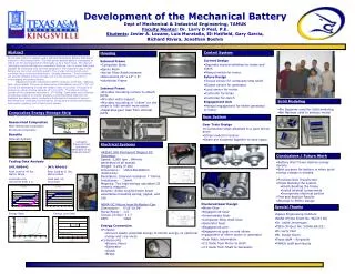
Development of the Mechanical Battery Dept of Mechanical & Industrial Engineering, TAMUK Faculty Mentor: Dr. Larry D Peel, P.E. Students: Javier A. Lozano, Luis Muratalla, Eli Hatfield, Gary Garcia, Richard Rivera, Jonathan Boehm Abstract Our project goal is to design a safe, efficient mechanical battery that stores energy in a mechanical form. The high power density battery is designed so that it can be recharged either electrically or by a hand crank. The manual recharging system will focus on provided a back-up form of power that could possibly be interfaced with exercise equipment. The materials used in this battery are non-toxic and light-weight. The energy will be stored using nonlinear fiber-reinforced elastomeric “storage elements.” These elements will provide efficient energy storage, but are also designed to prevent overcharging and battery failure. Objectives include making the battery relatively small size, relatively light, and portable. The current dimensions of the battery are 24” x 14” x 8” and we are attempting to keep the weight under 15 pounds. The goal is to achieve an energy storing capacity of 2.1 to 8 MJ. The desired energy density of the composite elements is .177 MJ/Kg. Team tasks have included conducting research on similar projects, contacting NASA engineers for feedback and design ideas, conducting finite element analysis of several fiber/elastomer composite combinations, developing a power transmission sub-system, gearing, and a hand-crank system. • Control System • Current Design • Separate manual switches for brake and clutch • Manual switch for motor • Future Design • Torque sensor for composite strip shaft • Output sensor for generator • Load sensor for motor • Controller for brake • Controller for clutch • Engagement Arm • Manual engagement for either generator or motor • Housing • External Frame • Composite Skins • Epoxy Resin • Kevlar Fiber Reinforcement • Dimensions 24” x 14” x 8” • Aluminum Frame • Internal Frame • Provides mounting surface to attach parts • Provides extra support • Provides mounting of “rollers” for the strips to fully stretch more easily • Separates gear train from internal parts • Solid Modeling • Pro Engineer used for Solid modeling • NeiNastran used to analyze model Composites Energy Storage Strip Research Researched Composites Fiber Reinforced Composites Structural Composites Benefits Materials Available Lightweight • Gear System • Gear Train Design • 4 Composite strips attached to a gear driven drum • Strips loaded in tension • Gears are clustered together to save space Composite Energy Storage Specimens Fabricated on the Filament Winder Electrical Systems 443542 20A Permanent Magnet DC Generator Speed: 5,000 rpm , 84Hertz generated at all speeds Weight: 4.2Kg (9.2lb) Dimensions : 150x150x300mm (6x6x12in). Resistance: Internal resistance 7.7ohms. Inductance: 16mH. Magnets: Two high-energy saturated C8 ceramic magnets. Brushes: Extra-long 8x14mm brush assemblies including spring, pigtail, and cap NEMA DC Motors from McMaster-Carr Dimensions : 5“x5”10.94“ Horse Power: 1/3 Torque (in-lbs): 11.7 RPM: 1800 • Conclusions / Future Work • Battery Won’t have desired energy density. • Best purpose for battery is when quick energy release is needed. • Purchase New Transformer • Finish Building the system • Finish Building the frame • Install internal components • Incorporate electrical portion • Test and Analyze Results • Attempt to Refine Design Testing Data Analysis IM7/RP6442 Peak Load at 49 lbs, Matrix Failed Load was only recovered from 2 in. IM7/RP6410 Peak Load at 11 lbs, Matrix Failed Load was not recovered • Clustered Gear Design • Motor Gear • Engagement Gear • Intermediate Gear • Composite Strip shaft Gear • Generator Gear • Engagement arm • Engagement gear on end allows engagement of either motor or generator • Gear Ratio Information • 2:1 Ratio from Motor to shaft • 4:1 Ratio from Shaft to Generator • Special Thanks • Space Engineering Institute • NASA (Prime Grant No. NCC9-150) • Dr. Judith Jeevarajan • TEES (Project No. 32566-681C3) • Dr. Larry Peel • Mr. Dustin Grant • Texas A&M – Kingsville • TAMUK staff and faculty Energy Data Energy Loss Data • Energy Conversion • Purpose: • Convert elastic potential energy to kinetic energy, to electrical energy and vice versa • Components • Electric Motor • Generator • Clutch • Brake