Download
1 / 22
220 likes | 337 Views
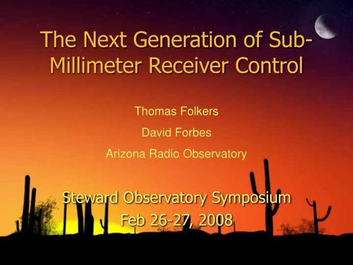
The Next Generation of Sub-Millimeter Receiver Control. Thomas Folkers David Forbes Arizona Radio Observatory. Steward Observatory Symposium Feb 26-27, 2008. Why Remote Receiver Control?. Allows: Remote Tuning Remote Diagnosis & Debugging Consistency in Training and Operation

E N D
The Next Generation of Sub-Millimeter Receiver Control Thomas Folkers David Forbes Arizona Radio Observatory Steward Observatory Symposium Feb 26-27, 2008
Why Remote Receiver Control? • Allows: • Remote Tuning • Remote Diagnosis & Debugging • Consistency in Training and Operation • Faster Frequency Changes and Setup
Receiver Control Design History • Designed in 1989 by NRAO for the 12 Meter • VxWorks VME Computer ($10,000) • DOS Based Interface • One User Interface Session Supported • Card Cage Interface to Hardware • Updated to SunOS/X11 Interface in 1992 • Design Revision in 2004 for JT System • Embedded Computer ($1,000) • PC104 I/O Cards (2 x $400) • Linux RH90 • Unlimited Number on User Interfaces Supported • Used Same Card Cage I/O Design • GTK User Interface
“JT” Control Design • Based on the NRAO Design • Separate Computer and Card Cage • Used Complete Linux Embedded System • PC104 I/O Cards • Active File System • Powering Off Caused Problems • 11 Processes Running in System • Required UPS Backup System • X11 User Interface can run on any Local host
New Integrated Design • Custom Embedded Controller Cards • No Active File-System • Only 2 Processes on Host Computer • Serial Comm Task • Interface Daemon • Share a Common Global Memory • Standardized Design • Used in the 345 & Future 650 and 950 GHz Systems. • Plans to retrofit 230 GHz “JT” system
Fully Integrated Card Cage System(345 GHz System Front View)
Fully Integrated Card Cage System(Analog - Digital I/O Card)
For Further Information: • ARO Web Site: • http://aro.as.arizona.edu/