Download
1 / 36
360 likes | 421 Views
Understand dynamic modeling and analysis in object-oriented systems, from use case scenarios to developing three-tier sequence diagrams for efficient software design. Learn the process step by step.

E N D
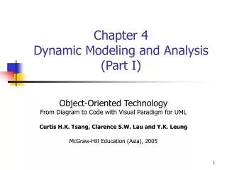
Chapter 4Dynamic Modeling and Analysis (Part II) Object-Oriented Technology From Diagram to Code with Visual Paradigm for UML Curtis H.K. Tsang, Clarence S.W. Lau and Y.K. Leung McGraw-Hill Education (Asia), 2005
Dynamic Analysis Techniques • How can we transform from “what the system does” (requirements) to “how the system is implemented”? (implementation) • Use case captures the external observable behaviors of the system. • Need to know what objects are involved. • Source of hints: • User interactions with the system • Boundary objects • Information retrieval/updated • Entity objects • Management of control flow and transaction • control objects • Data transformation, algorithm, etc. • other utility objects
Dynamic Analysis Techniques (cont’d) • Three steps for developing sequence diagram: • Modeling External System Behaviors • Modeling Communication among the Subsystems • Developing Reusable Model/View/Control (MVC) Software Framework
Modeling External System Behaviors • As the flow of events in the use case description only records the external behaviors of the system and identifies the user inputs and system responses from the flow of events of a scenario, it is a straightforward process to map the scenario to a system-level sequence diagram. • In fact, this mapping process can be automated by a UML CASE tool.
Modeling Communication among the Subsystems • Modeling and analyzing complex systems often involve many objects even for the realization of a single use case. • To develop a detailed sequence diagram based on the system-level sequence diagram with sufficient information for implementation in one go generally requires a lot of effort. • In order to manage the complexity associated with large and complex systems, it is advantageous to package objects into several subsystems. • For example, an ATM system may be organized as a number of subsystems like the ATM, the bank consortium and the bank. Such an organization also reflects how the real-world hardware and software systems are configured, since the ATMs are connected to the bank consortium’s system which is in turn connected to the systems of individual banks.
Developing Reusable Model/View/Control (MVC) Software Framework • At this point you will have developed the system-level sequence diagram and may have also developed a subsystem-level sequence diagram. • We should then develop a detailed sequence diagram in three tiers, involving three types of objects: boundary, control and entity objects.
The Dynamic Modeling and Analysis Process • Developing use case scenarios • Developing system-level sequence diagrams • Developing subsystem-level sequence diagrams (optional for simple system) • Developing subsystem-level statechart diagrams (optional for simple system) • Developing three-tier sequence diagrams • Developing three-tier collaboration diagrams (optional) • Developing a statechart diagram for each of these active (control) objects
Developing Use Case Scenarios • Example – ATM System • Flow of Events • User inserts card • System prompts user to enter PIN • User enters PIN • System prompts user to select services • User selects service - withdraw money • System prompts user to enter withdrawal amount • User enters withdrawal amount • System displays “withdrawal successful” message, ejects card and dispenses money • User collects card and money
Developing Subsystem-level Statechart diagram • With the subsystem-level sequence diagram created in Step 2, we can develop the subsystem-level statechart diagram for the scenario. • Let us again use the ATM as an example. When the ATM is idle, it shows a main screen, for example, the welcome screen. • If the user inserts a valid ATM card, it will display a “wait for input PIN” screen.
Developing Three-tier Sequence Diagrams • Identify Boundary, Control and Entity Objects • Message to and from the actor => boundary objects, e.g. insert card => card reader • Information retrieval/ update => entity object, e.g. verify card => account • Management of transaction => control objects, e.g. ATM controller
Developing Statechart Diagrams for Control Objects Statechart diagram of the Card Controller
Tricks and Tips • Creating Cohesive and Self-sufficient Subsystems • Subsystems may be considered as the next level of abstraction down from the entire system. • Ideally, a subsystem should be a cohesive and independent part of the complex system, so as to bring out the benefits of portability, reusability and maintainability. • A cohesive and independent subsystem is loosely coupled with other subsystems, and data coupling is the most loosely-coupled communication method between entities.
Tricks and Tips (cont’d) • Refining Class Diagrams Using MVC-level Scenario Analysis
Tricks and Tips (cont’d) • Understanding System Reusability for Different Types of Objects
Tricks and Tips (cont’d) • Do Not Create Giant Control Objects • the control sequence of messages in the scenario; • information about the sessions in relation to the use case scenario, e.g. session ID, session status, etc.; • control logic of the run-time session, e.g. transaction management, error recovery, etc.
Tricks and Tips (cont’d) • Checking Consistency between Use Case and Sequence Diagrams