Mastering Dynamic Modeling with UML Sequences
460 likes | 492 Views
Learn how to identify classes and behaviors from dynamic models using UML sequence and state diagrams. Discover how events drive interactions between objects and delve into heuristics for creating effective sequence diagrams.

Mastering Dynamic Modeling with UML Sequences
E N D
Presentation Transcript
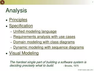
Chapter 5: Analysis Dynamic Modeling
Outline of the Lecture • Dynamic modeling • Sequence diagrams • State diagrams • Using dynamic modeling for the design of user interfaces • Analysis example • Requirements analysis document template
How do you find classes? • In previous lectures we have already established the following sources • Application domain analysis: Talk to client to identify abstractions • Application of general world knowledge and intuition • Scenarios • Natural language formulation of a concrete usage of the system • Use Cases • Natural language formulation of the functions of the system • Textual analysis of problem statement (Abbott) • Today we show how identify classes from dynamic models • Actions and activities in state chart diagrams are candidates for public operations in classes • Activity lines in sequence diagrams are also candidates for objects
Dynamic Modeling with UML • Diagrams for dynamic modeling • Interaction diagrams describe the dynamic behavior between objects • Statecharts describe the dynamic behavior of a single object • Interaction diagrams • Sequence Diagram: • Dynamic behavior of a set of objects arranged in time sequence. • Good for real-time specifications and complex scenarios • Collaboration Diagram : • Shows the relationship among objects. Does not show time • State Chart Diagram: • A state machine that describes the response of an object of a given class to the receipt of outside stimuli (Events). • Activity Diagram: A special type of statechart diagram, where all states are action states (Moore Automaton)
Dynamic Modeling • Purpose: • Detect and supply methods for the object model • How do we do this? • Start with use case or scenario • Model interaction between objects => sequence diagram • Model dynamic behavior of a single object => statechart diagram
Start with Flow of Events from Use Case • Flow of events from “Dial a Number” Use case: • Caller lifts receiver • Dial tone begins • Caller dials • Phone rings • Callee answers phone • Ringing stops • ....
What is an Event? • Something that happens at a point in time • Relation of events to each other: • Causally related: Before, after, • Causally unrelated: concurrent • An event sends information from one object to another • Events can be grouped in event classes with a hierarchical structure. ‘Event’ is often used in two ways: • Instance of an event class: “New IETM issued on Thursday September 14 at 9:30 AM”. • Event class “New IETM” • Attribute of an event class • IETM Update (9:30 AM, 9/14/99) • Car starts at ( 4:45pm, Monroeville Mall, Parking Lot 23a) • Mouse button down(button#, tablet-location)
Sequence Diagram • From the flow of events in the use case or scenario proceed to the sequence diagram • A sequence diagram is a graphical description of objects participating in a use case or scenario using a DAG (direct acyclic graph) notation • Relation to object identification: • Objects/classes have already been identified during object modeling • Objects are identified as a result of dynamic modeling • Heuristic: • A event always has a sender and a receiver. • The representation of the event is sometimes called a message • Find them for each event => These are the objects participating in the use case
An Example • Flow of events in a “Get SeatPosition” use case : 1. Establish connection between smart card and onboard computer 2. Establish connection between onboard computer and sensor for seat 3. Get current seat position and store on smart card • Which are the objects?
Sequence Diagram for “Get SeatPosition” Seat Onboard Computer Smart Card • 1. Establish connection between smart card and onboard computer • 2. Establish connection between onboard computer and sensor for seat • 3. Get current seat position and store on smart card Establish Connection Establish Connection Accept Connection Accept Connection Get SeatPosition “500,575,300” time
Heuristics for Sequence Diagrams • Layout: • 1st column: Should correspond to the actor who initiated the use case • 2nd column: Should be a boundary object • 3rd column: Should be the control object that manages the rest of the use case • Creation: • Boundary objects are created at the initiation of a use case • Control objects are created by boundary objects • Access: • Entity objects are accessed by control and boundary objects, • Entity objects should never call boundary or control objects: This makes it easier to share entity objects across use cases and makes entity objects resilient against technology-induced changes in boundary objects.
Is this a good Sequence Diagram? Seat Onboard Computer Smart Card • First column is not the actor • It is not clear where the boundary object is • It is not clear where the control object is Establish Connection Establish Connection Accept Connection Accept Connection Get SeatPosition “500,575,300”
Example - ARENA: The Problem • The Internet has enabled virtual communities • Groups of people sharing common of interests but who have never met each other in person. Such virtual communities can be short lived (e.g people in a chat room or playing a multi player game) or long lived (e.g., subscribers to a mailing list). • Many multi-player computer games now include support for virtual communities. • Players can receive news about game upgrades, new game levels, announce and organize matches, and compare scores. • Currently each game company develops such community support in each individual game. • Each company uses a different infrastructure, different concepts, and provides different levels of support. • This redundancy and inconsistency leads to problems: • High learning curve for players joining a new community, • Game companies need to develop the support from scratch • Advertisers need to contact each individual community separately.
Example - ARENA: The Objectives • Provide a generic infrastructure for operating an arena to • Support virtual game communities. • Register new games • Register new players • Organize tournaments • Keeping track of the players scores. • Provide a framework for tournament organizers • to customize the number and sequence of matchers and the accumulation of expert rating points. • Provide a framework for game developers • for developing new games, or for adapting existing games into the ARENA framework. • Provide an infrastructure for advertisers.
:Tournament :Arena :League Boundary League Owner newTournament (league) :Announce «new» Tournament Control checkMax Tournament() setName(name) setMaxPlayers (maxp) create Tournament (name, maxp) commit() createTournament (name, maxp) «new» :Tournament An ARENA Sequence Diagram : Create Tournament
Impact on ARENA’s Object Model • Let’s assume, before we formulated the previous sequence diagram, ARENA’s object model contained the objects • League Owner, Arena, League, Tournament, Match and Player • The Sequence Diagram identified new Classes • Tournament Boundary, Announce_Tournament_Control
League Owner League 1 * Attributes Attributes Operations Operations Tournament Attributes Operations Player Match * * Attributes Attributes Operations Operations
Tournament_ Boundary Announce_ Tournament_ Control Attributes Operations Attributes Operations League Owner League 1 * Attributes Attributes Operations Operations Tournament Attributes Operations Player Match * * Attributes Attributes Operations Operations
Impact on ARENA’s Object Model (ctd) • The Sequence Diagram also supplied us with a lot of new events • newTournament(league) • setName(name) • setMaxPlayers(max) • Commit • checkMaxTournaments() • createTournament • Question: Who owns these events? • Answer: For each object that receives an event, there is a public operation in the associated class. • The name of the operation is usually the name of the event.
:Tournament :Arena :League Boundary League Owner newTournament (league) :Announce «new» Tournament Control checkMax Tournament() setName(name) setMaxPlayers (maxp) create Tournament (name, maxp) commit() «new» :Tournament Example from the Sequence Diagram createTournament is a (public) operation owned by Announce_Tournament_Control createTournament (name, maxp)
Tournament_ Boundary Attributes Operations League Owner League 1 * Attributes Attributes Operations Operations Tournament Announce_ Tournament_ Control Attributes Operations Attributes createTournament (name, maxp) Player Match * * Attributes Attributes Operations Operations
What else can we get out of sequence diagrams? • Sequence diagrams are derived from the use cases. We therefore see the structure of the use cases. • The structure of the sequence diagram helps us to determine how decentralized the system is. • We distinguish two structures for sequence diagrams: Fork and Stair Diagrams (Ivar Jacobsen)
Fork Diagram • Much of the dynamic behavior is placed in a single object, usually the control object. It knows all the other objects and often uses them for direct questions and commands.
Stair Diagram • The dynamic behavior is distributed. Each object delegates some responsibility to other objects. Each object knows only a few of the other objects and knows which objects can deal with a specific behavior.
Fork or Stair? • Which of these diagram types should be chosen? • Object-oriented fans claim that the stair structure is better • The more the responsibility is spread out, the better • However, this is not always true. Better heuristics: • Decentralized control structure • The operations have a strong connection • The operations will always be performed in the same order • Centralized control structure (better support of change) • The operations can change order • New operations can be inserted as a result of new requirements
UML Statechart Diagram Notation Event trigger With parameters • Notation based on work by Harel • Added are a few object-oriented modifications • A UML statechart diagram can be mapped into a finite state machine State1 State2 Event1(attr) [condition]/action do/Activity Guard condition entry /action exit/action Also: internal transition and deferred events
Statechart Diagrams • Graph whose nodes are states and whose directed arcs are transitions labeled by event names. • We distinguish between two types of operations in statecharts: • Activity: Operation that takes time to complete • associated with states • Action: Instantaneous operation • associated with events • associated with states (reduces drawing complexity): Entry, Exit, Internal Action • A statechart diagram relates events and states for one class • An object model with a set of objects has a set of state diagrams An Example: http://bdn.borland.com/article/0,1410,31863,00.html#statechart-diagrams
State • An abstraction of the attributes of a class • State is the aggregation of several attributes of a class • Basically an equivalence class of all those attribute values and links that do not need to be distinguished as far as the control structure of the system is concerned • Example: State of a bank • A bank is either solvent or insolvent • State has duration
coins_in(amount) / set balance Idle cancel / refund coins [item empty] select(item) [change<0] do: test item and compute change [change>0] [change=0] do: dispense item do: make change Example of a StateChart Diagram coins_in(amount) / add to balance Collect Money
Nested State Diagram • Activities in states are composite items denoting other lower-level state diagrams • A lower-level state diagram corresponds to a sequence of lower-level states and events that are invisible in the higher-level diagram. • Sets of substates in a nested state diagram denote a superstate are enclosed by a large rounded box, also called contour.
coins_in(amount) / set balance Collect Money Idle coins_in(amount) / add to balance cancel / refund coins [item empty] select(item) [change<0] Superstate do: test item and compute change [change>0] [change=0] do: make change Example of a Nested Statechart Diagram do: dispense item
Superstate [change=0] Example of a Nested Statechart Diagram do: dispense item
arm ready arm ready Example of a Nested Statechart Diagram ‘Dispense item’ as a composite activity: ‘Dispense item’ as an atomic activity: do: move arm to row do: move arm to column do: dispense item do: push item off shelf
Expanding activity “do:dispense item” ‘Dispense item’ as an atomic activity: [change=0] do: dispense item ‘Dispense item’ as a composite activity: do: move arm to row do: push item off shelf do: move arm to column arm ready arm ready
Dispense item do: move arm to row do: push item off shelf do: move arm to column arm ready arm ready Out of order Superstates • Reduce the number of lines in a state diagram • Transitions from other states to the superstate enter the first substate of the superstate. • Transitions to other states from a superstate are inherited by all the substates (state inheritance)
Modeling Concurrency Two types of concurrency 1. System concurrency • Each object’s state diagram is executing concurrently with the others. 2. Object concurrency • An object can be partitioned into subsets of states (attributes and links) such that each of them has its own subdiagram. • The state of the object consists of a set of states: one state from each subdiagram. • State diagrams are divided into subdiagrams by dotted lines.
Example of Concurrency within an Object Splitting control Synchronization Emitting Do: Dispense Cash taken Cash Ready Setting to r eset Up Ready Do: Eject Card Card taken
State Chart Diagram vs Sequence Diagram • State chart diagrams help to identify: • Changes to an individual object over time • Sequence diagrams help to identify • The temporal relationship of between objects over time • Sequence of operations as a response to one ore more events
Dynamic Modeling of User Interfaces • Statechart diagrams can be used for the design of user interfaces • Also called Navigation Path • States: Name of screens • Graphical layout of the screens associated with the states helps when presenting the dynamic model of a user interface • Activities/actions are shown as bullets under screen name • Often only the exit action is shown • State transitions: Result of exit action • Button click • Menu selection • Cursor movements • Good for web-based user interface design
Navigation Path Example • Diagnostics Menu • User moves cursor to Control Panel or Graph • Graph • User selects data group and type of graph • Control panel • User selects functionality of sensors • Selection • User selects data group • Field site • Car • Sensor group • Time range • User selects type of graph • time line • histogram • pie chart • Define • User defines a sensor event • from a list of events • Disable • User can disable a sensor event from a list of sensor events • Enable • User can enable a sensor event from a list of sensor events • List of events • User selects event(s) • Visualize • User views graph • User can add data groups for being viewed • List of sensor events • User selects sensor event(s) • Link • User makes a link (doclink)
Practical Tips for Dynamic Modeling • Construct dynamic models only for classes with significant dynamic behavior • Avoid “analysis paralysis” • Consider only relevant attributes • Use abstraction if necessary • Look at the granularity of the application when deciding on actions and activities
Come back to the “dial a number” example • Flow of events from “Dial a Number” Use case: • Caller lifts receiver • Dial tone begins • Caller dials • Phone rings • Callee answers phone • Ringing stops • .... Sequence diagram State chart diagram
Functional Modeling Object Modeling Dynamic Modeling Summary: Requirements Analysis • 1. What are the transformations? • Create scenarios and use case diagrams • Talk to client, observe, get historical records, do thought experiments • 2. What is the structure of the system? • Create class diagrams • Identify objects. • What are the associations between them? What is their multiplicity? • What are the attributes of the objects? • What operations are defined on the objects? • 3. What is its behavior? • Create sequence diagrams • Identify senders and receivers • Show sequence of events exchanged between objects. Identify event dependencies and event concurrency. • Create state diagrams • Only for the dynamically interesting objects.
Requirements Analysis Document Template 1. Introduction 2. Current system 3. Proposed system 3.1 Overview 3.2 Functional requirements 3.3 Nonfunctional requirements 3.4 Constraints (“Pseudo requirements”) 3.5 System models 3.5.1 Scenarios 3.5.2 Use case model 3.5.3 Object model 3.5.3.1 Data dictionary 3.5.3.2 Class diagrams 3.5.4 Dynamic models 3.5.5 User interface 4. Glossary
Section 3.5 System Model 3.5.1 Scenarios - As-is scenarios, visionary scenarios 3.5.2 Use case model - Actors and use cases 3.5.3 Object model - Data dictionary - Class diagrams (classes, associations, attributes and operations) 3.5.4 Dynamic model - State diagrams for classes with significant dynamic behavior - Sequence diagrams for collaborating objects (protocol) 3.5.5 User Interface - Navigational Paths, Screen mockups