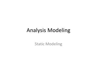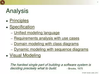
Chapter 5, Analysis: Dynamic Modeling
370 likes | 404 Views
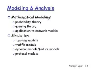
Chapter 5, Analysis: Dynamic Modeling. Outline of the Lecture. Dynamic modeling Interaction Diagrams Sequence diagrams Collaboration diagrams State diagrams

Chapter 5, Analysis: Dynamic Modeling
E N D
Presentation Transcript
Outline of the Lecture • Dynamic modeling • Interaction Diagrams • Sequence diagrams • Collaboration diagrams • State diagrams • Activity diagrams (UD: interestingly, our book continues to ignore their significance; considers as a special case of State diagrams!) • Requirements analysis model validation
How do you find classes? • We have already established several sources for class identification: • Application domain analysis: We find classes by talking to the client and identify abstractions by observing the end user • General world knowledge and intuition • Textual analysis of event flow in use cases (Abbot) • Today we identify classes from dynamic models • Two good heuristics: • Activity lines in sequence diagrams are candidates for objects • Actions and activities in state chart diagrams are candidates for public operations in classes
Dynamic Modeling • Definition of a dynamic model: • Describes the components of the system that have interesting dynamic behavior • The dynamic model is described with • State diagrams: One state diagram for each class with interesting dynamic behavior • Classes without interesting dynamic behavior are not modeled with state diagrams • Sequence diagrams: For the interaction between classes • Activity diagrams: Model the (complex) logic (business rules) captured by a use case • Purpose: • Detect and supply operations for the object model.
How do we detect Operations? • We look for objects, who are interacting and extract their “protocol” • We look for objects, who have interesting behavior on their own • Good starting point: Flow of events in a use case description • From the flow of events we proceed to the sequence diagram to find the participating objects.
What is an Event? • Something that happens at a point in time • An event sends information from one object to another • Events can have associations with each other: • Causally related: • An event happens always before another event • An event happens always after another event • Causally unrelated: • Events that happen concurrently • Events can also be grouped in event classes with a hierarchical structure => Event taxonomy
Sequence Diagram • A sequence diagram is a graphical description of the objects participating in a use case using a DAG notation • Heuristic for finding participating objects: • A event always has a sender and a receiver • Find them for each event => These are the objects participating in the use case.
An Example • Flow of events in “Get SeatPosition” use case : 1. Establish connection between smart card and onboard computer 2. Establish connection between onboard computer and sensor for seat 3. Get current seat position and store on smart card • Where are the objects?
Smart Card Onboard Computer Seat Establish Connection Establish Connection Accept Connection Accept Connection Get SeatPosition “500,575,300” time Sequence Diagram for “Get SeatPosition” • 1. Establish connection between smart card and onboard computer • 2. Establish connection between onboard computer and seat (actually seat sensor) • 3. Get current seat position and store on smart card.
Heuristics for Sequence Diagrams • Layout: • 1st column: Should be the actor of the use case • 2nd column: Should be a boundary object • 3rd column: Should be the controlobject that manages the rest of the use case • Creation of objects: • Create control objects at beginning of event flow • The control objects create the boundary objects • Access of objects: • Entity objects can be accessed by control and boundary objects • Entity objects should not access boundary or control objects.
:Tournament :Arena :League Boundary League Owner newTournament (league) :Announce «new» Tournament Control checkMax Tournament() setName(name) setMaxPlayers (maxp) create Tournament (name, maxp) commit() createTournament (name, maxp) «new» :Tournament ARENA Sequence Diagram: Create Tournament
Impact on ARENA’s Object Model • Let’s assume ARENA’s object model contains - at this modeling stage - the objects • League Owner, Arena, League, Tournament, Match and Player • The Sequence Diagram identifies 2 new Classes • Tournament Boundary, Announce_Tournament_Control
League Owner League 1 * Attributes Attributes Operations Operations Tournament Attributes Operations Player Match * * Attributes Attributes Operations Operations
Tournament_ Boundary Announce_ Tournament_ Control Attributes Operations Attributes Operations League Owner League 1 * Attributes Attributes Operations Operations Tournament Attributes Operations Player Match * * Attributes Attributes Operations Operations
Impact on ARENA’s Object Model (2) • The sequence diagram also supplies us with many new events • newTournament(league) • setName(name) • setMaxPlayers(max) • commit • checkMaxTournament() • createTournament • Question: • Who owns these events? • Answer: • For each object that receives an event there is a public operation in its associated class • The name of the operation is usually the name of the event.
:Tournament :Arena :League Boundary League Owner newTournament (league) :Announce «new» Tournament Control checkMax Tournament() setName(name) setMaxPlayers (maxp) commit() «new» :Tournament Example from the Sequence Diagram create Tournament (name, maxp) createTournament (name, maxp)
Tournament_ Boundary Attributes Operations createTournament (name, maxp) League Owner League 1 * Attributes Attributes Operations Operations Tournament Announce_ Tournament_ Control Attributes Operations Attributes Player Match * * Attributes Attributes Operations Operations
Dynamic Modeling • We distinguish between two types of operations: • Activity: Operation that takes time to complete • associated with states • Action: Instantaneous operation • associated with events • A state chart diagram relates events and states for one class • An object model with several classes with interesting behavior has a set of state diagrams
State1 State2 UML Statechart Diagram Notation Action Name of State Event with parameters attr • Note: • Events are italics • Conditions are enclosed with brackets: [] • Actions and activities are prefixed with a slash / • Notation is based on work by Harel • Added are a few object-oriented modifications. Event Event(attr) [condition]/action do/Activity Guard condition entry /action exit/action Actions and Activities in State
coins_in(amount) / set balance Collect Money Idle coins_in(amount) / add to balance cancel / refund coins [item empty] [select(item)] [change<0] do/Test item and compute change [change>0] [change=0] do/Dispense item do/Make change Example of a StateChart Diagram
State • An abstraction of the attributes of a class • State is the aggregation of several attributes a class • A state is an equivalence class of all those attribute values and links that do no need to be distinguished • Example: State of a bank • State has duration
Activity Diagrams • An activity diagram is useful to depict the workflow in a system
Activity Diagrams can model Concurrency • Synchronization of multiple activities • Splitting the flow of control into multiple threads Splitting Synchronization
Activity Diagrams: Grouping of Activities • Activities may be grouped into swimlanes to denote the object or subsystem that implements the activities. Dispatcher Allocate Resources Open Coordinate Archive Incident Resources Incident FieldOfficer Document Incident
Practical Tips for Dynamic Modeling • Construct dynamic models only for classes with significant dynamic behavior • Avoid “analysis paralysis” • Consider only relevant attributes • Use abstraction if necessary • Look at the granularity of the application when deciding on actions and activities • Reduce notational clutter • Try to put actions into superstate boxes (look for identical actions on events leading to the same state).
Model Validation and Verification • Verification is an equivalence check between the transformation of two models • Validation is the comparison of the model with reality • Validation is a critical step in the development process Requirements should be validated with the client and the user. • Techniques: Formal and informal reviews (Meetings, requirements review) • Requirements validation involves several checks • Correctness, Completeness, Ambiguity, Realistism
Checklist for a Requirements Review • Is the model correct? • A model is correct if it represents the client’s view of the system • Is the model complete? • Every scenario is described • Is the model consistent? • The model does not have components that contradict each other • Is the model unambiguous? • The model describes one system, not many • Is the model realistic? • The model can be implemented
Examples for syntactical Problems • Different spellings in different UML diagrams • Omissions in diagrams
League Owner League 1 * Attributes Attributes Operations Operations createTournament (name, maxp) Tournament_ Boundary Tournament Announce_ Tournament_ Control Attributes Attributes Operations Operations Attributes makeTournament (name, maxp) Different spellings in different models for the same operation Player Match * * Attributes Attributes Operations Operations Different spellings in different UML diagrams UML Sequence Diagram UML Class Diagram
Checklist for the Requirements Review (2) • Syntactical check of the models • Check for consistent naming of classes, attributes, methods in different subsystems • Identify dangling associations (“pointing to nowhere”) • Identify double- defined classes • Identify missing classes (mentioned in one model but not defined anywhere) • Check for classes with the same name but different meanings
When is a Model Dominant? • Object model: • The system has classes with nontrivial states and many relationships between the classes • Dynamic model: • The model has many different types of events: Input, output, exceptions, errors, etc. • Functional model: • The model performs complicated transformations (e.g. computations consisting of many steps). • Which model is dominant in these applications? • Compiler • Database system • Spreadsheet program
Examples of Dominant Models • Compiler: • The functional model is most important • The dynamic model is trivial because there is only one type input and only a few outputs • Is that true for IDEs? • Database systems: • The object model most important • The functional model is trivial, because the purpose of the functions is to store, organize and retrieve data • Spreadsheet program: • The functional model most important • The dynamic model is interesting if the program allows computations on a cell • The object model is trivial.
Requirements Analysis Document Template 1. Introduction 2. Current system 3. Proposed system 3.1 Overview 3.2 Functional requirements 3.3 Nonfunctional requirements 3.4 Constraints (“Pseudo requirements”) 3.5 System models 3.5.1 Scenarios 3.5.2 Use case model 3.5.3 Object model 3.5.3.1 Data dictionary 3.5.3.2 Class diagrams 3.5.4 Dynamic models 3.5.5 User interfae 4. Glossary
Section 3.5 System Model 3.5.1 Scenarios - As-is scenarios, visionary scenarios 3.5.2 Use case model - Actors and use cases 3.5.3 Object model - Data dictionary - Class diagrams (classes, associations, attributes and operations) 3.5.4 Dynamic model - State diagrams for classes with significant dynamic behavior • Sequence diagrams for collaborating objects (protocol) • Activity diagrams for complex business rules/logic 3.5.5 User Interface - Navigational Paths, Screen mockups
Functional Modeling Object Modeling Dynamic Modeling Requirements Analysis Questions 1. What are the transformations? Create scenarios and use case diagrams • Talk to client, observe, get historical records 2. What is the structure of the system? Create class diagrams • Identify objects. Associations between them? Their multiplicity? • What are the attributes of the objects? Operations on the objects? • 3. What is its behavior? Create sequence diagrams • Identify senders and receivers • Show sequence of events exchanged between objects. • Identify event dependencies and event concurrency. Create state diagrams • Only for the dynamically interesting objects. Create activity diagrams
Summary • In this lecture, we reviewed the construction of the dynamic model from use case and object models. In particular, we described: • Sequence and statechart diagrams for identifying new classes and operations. • Activity diagrams for describing complex business rules/logic inside operations. • In addition, we described the requirements analysis document and its components.