Chapter 19 Resonant Conversion
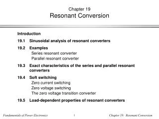
Chapter 19 Resonant Conversion. Introduction 19.1 Sinusoidal analysis of resonant converters 19.2 Examples Series resonant converter Parallel resonant converter 19.3 Exact characteristics of the series and parallel resonant converters 19.4 Soft switching Zero current switching

Chapter 19 Resonant Conversion
E N D
Presentation Transcript
Chapter 19Resonant Conversion • Introduction • 19.1 Sinusoidal analysis of resonant converters • 19.2 Examples • Series resonant converter • Parallel resonant converter • 19.3 Exact characteristics of the series and parallel resonant converters • 19.4 Soft switching • Zero current switching • Zero voltage switching • The zero voltage transition converter • 19.5 Load-dependent properties of resonant converters
Introduction to Resonant Conversion • Resonant power converters contain resonant L-C networks whose voltage and current waveforms vary sinusoidally during one or more subintervals of each switching period. These sinusoidal variations are large in magnitude, and the small ripple approximation does not apply. • Some types of resonant converters: • Dc-to-high-frequency-ac inverters • Resonant dc-dc converters • Resonant inverters or rectifiers producing line-frequency ac
A basic class of resonant inverters Basic circuit Several resonant tank networks
Tank network responds only to fundamental component of switched waveforms Tank current and output voltage are essentially sinusoids at the switching frequency fs. Output can be controlled by variation of switching frequency, closer to or away from the tank resonant frequency
An electronic ballast • Must produce controllable high-frequency (50 kHz) ac to drive gas discharge lamp • DC input is typically produced by a low-harmonic rectifier • Similar to resonant dc-dc converter, but output-side rectifier is omitted Half-bridge, driving LCC tank circuit and gas discharge lamp
Derivation of a resonant dc-dc converter Rectify and filter the output of a dc-high-frequency-ac inverter The series resonant dc-dc converter
A series resonant link inverter Same as dc-dc series resonant converter, except output rectifiers are replaced with four-quadrant switches:
Resonant conversion: advantages • The chief advantage of resonant converters: reduced switching loss • Zero-current switching • Zero-voltage switching • Turn-on or turn-off transitions of semiconductor devices can occur at zero crossings of tank voltage or current waveforms, thereby reducing or eliminating some of the switching loss mechanisms. Hence resonant converters can operate at higher switching frequencies than comparable PWM converters • Zero-voltage switching also reduces converter-generated EMI • Zero-current switching can be used to commutate SCRs • In specialized applications, resonant networks may be unavoidable • High voltage converters: significant transformer leakage inductance and winding capacitance leads to resonant network
Resonant conversion: disadvantages Can optimize performance at one operating point, but not with wide range of input voltage and load power variations Significant currents may circulate through the tank elements, even when the load is disconnected, leading to poor efficiency at light load Quasi-sinusoidal waveforms exhibit higher peak values than equivalent rectangular waveforms These considerations lead to increased conduction losses, which can offset the reduction in switching loss Resonant converters are usually controlled by variation of switching frequency. In some schemes, the range of switching frequencies can be very large Complexity of analysis
Resonant conversion: Outline of discussion • Simple steady-state analysis via sinusoidal approximation • Simple and exact results for the series and parallel resonant converters • Mechanisms of soft switching • Resonant inverter design techniques. Circulating currents, and the dependence (or lack thereof) of conduction loss on load power • Following this chapter: extension of sinusoidal analysis techniques to model control system dynamics and small-signal transfer functions
19.1 Sinusoidal analysis of resonant converters A resonant dc-dc converter: If tank responds primarily to fundamental component of switch network output voltage waveform, then harmonics can be neglected. Let us model all ac waveforms by their fundamental components.
The sinusoidal approximation Tank current and output voltage are essentially sinusoids at the switching frequency fs. Neglect harmonics of switch output voltage waveform, and model only the fundamental component. Remaining ac waveforms can be found via phasor analysis.
19.1.1 Controlled switch network model If the switch network produces a square wave, then its output voltage has the following Fourier series: The fundamental component is So model switch network output port with voltage source of value vs1(t)
Model of switch network input port Assume that switch network output current is It is desired to model the dc component (average value) of the switch network input current.
Switch network: equivalent circuit • Switch network converts dc to ac • Dc components of input port waveforms are modeled • Fundamental ac components of output port waveforms are modeled • Model is power conservative: predicted average input and output powers are equal
19.1.2 Modeling the rectifier and capacitive filter networks Assume large output filter capacitor, having small ripple. vR(t) is a square wave, having zero crossings in phase with tank output current iR(t). If iR(t) is a sinusoid: Then vR(t) has the following Fourier series:
Sinusoidal approximation: rectifier Again, since tank responds only to fundamental components of applied waveforms, harmonics in vR(t) can be neglected. vR(t) becomes Actual waveforms with harmonics ignored
Rectifier dc output port model Output capacitor charge balance: dc load current is equal to average rectified tank output current Hence
Equivalent circuit of rectifier • Rectifier input port: • Fundamental components of current and voltage are sinusoids that are in phase • Hence rectifier presents a resistive load to tank network • Effective resistance Re is Rectifier equivalent circuit With a resistive load R, this becomes
19.1.3 Resonant tank network Model of ac waveforms is now reduced to a linear circuit. Tank network is excited by effective sinusoidal voltage (switch network output port), and is load by effective resistive load (rectifier input port). Can solve for transfer function via conventional linear circuit analysis.
Solution of tank network waveforms Transfer function: Ratio of peak values of input and output voltages: Solution for tank output current: which has peak magnitude
19.1.4 Solution of convertervoltage conversion ratio M = V/Vg Eliminate Re:
Conversion ratio M So we have shown that the conversion ratio of a resonant converter, having switch and rectifier networks as in previous slides, is equal to the magnitude of the tank network transfer function. This transfer function is evaluated with the tank loaded by the effective rectifier input resistance Re.