Download
1 / 26
280 likes | 655 Views
Resonant Circuits. SEE 1023 Circuit Theory. Frequency Response. L. R. I. + V L -. + V R -. + V C -. V s. C. w (varied). Series RLC Circuit. When w varies, the impedance of the circuit will vary. Then, the current and the real power will also vary.

E N D
Resonant Circuits SEE 1023 Circuit Theory Frequency Response
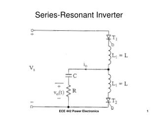
L R I + VL - + VR - + VC - Vs C w (varied) Series RLC Circuit When w varies, the impedance of the circuit will vary. Then, the current and the real power will also vary. We would like to study the frequency response of these quantities.
Impedance as a function of frequency: Current as a function of frequency: Reactance as a function of frequency: Power as a function of frequency: Series RLC Circuit
Series RLC Circuit Series RLC Circuit Response (Output) Excitation (Input) Constant input voltage: Vs Variable Source angular frequency: w Main response: current Other responses: Power, Impedance, reactance, etc.
L R I + VL - + VR - + VC - Vs C w (varied) Series RLC Circuit in PSpice 2 3 1 0 It is too hard to study the frequency response of these quantities manually. It is too easy to study the frequency response of these quantities PSpicely.
To Display graph End FREQ. Total PTS. Start FREQ. Series RLC Circuit in PSpice Series resonant Circuit Vs 1 0 AC 10V R1 1 2 10 L1 2 3 100mH C1 3 0 10uF .AC LIN 1001 100Hz 220Hz .Probe .end
In the Probe windows Trace Expression Response M(V(1)/I(R1)) Magnitude of Z P(V(1)/I(R1)) Phase of Z R(V(1)/I(R1)) Real part of Z Imaginary part of Z IMG(V(1)/I(R1))
In the Probe windows Trace Expression Response M(I(R1)) Magnitude of I P(I(R1)) Phase of I R(I(R1)) Real part of I Imaginary part of I IMG(I(R1))
In the Probe windows Trace Expression Response V(1,2) Magnitude of VR V(2,3) Magnitude of VL V(3) Magnitude of VC Real power, P I(R1)*I(R1)*10
Frequency Response of The Current Run Pspice File
Frequency Response of The Current (Variation of the current with frequency) At Resonance, the current is maximum At Resonance, the current is maximum
Basic Questions Z= R What is the minimum value of Z? What is the maximum value of I? What is the maximum value of P?
Basic Questions When the power P = Po/2, what is The angular frequency? w1 lower half power frequency w2 higher half power frequency The magnitude of I? The magnitude of Z? at w1 The magnitude of X? at w2
Resonant Condition • By definition the resonant angular frequency, wo, for the RLC series circuit occurs at the peak of the current response. Under this condition: • The real power is maximum • The magnitude of impedance is minimum • The circuit is purely resistive • The imaginary part of the impedance is zero • The pf = 1 • The current is in phase with the voltage source
Lower half-power angular frequency, w1, condition • By definition lower half-power angular frequency, w1, occurs when the power is Po/2 and the angular frequency is below the resonant angular frequency. • The real power is Po/2 • The current is Io /2 • The magnitude of impedance is 2R • X = -R • The circuit is predominantly capacitive • The pf = cos(45) leading
Lower half-power angular frequency, w2, condition • By definition lower half-power angular frequency, w2, occurs when the power is Po/2 and the angular frequency is above the resonant angular frequency. • The real power is Po/2 • The current is Io /2 • The magnitude of impedance is 2R • X = +R • The circuit is predominantly inductive • The pf = cos(45) lagging
The Voltage Phasor Diagram at wo For R: I is in phase with VR For L: I lags VL by 90 For C: I leads VC by 90 For series circuit, use I as the reference. VL at wo VR = VS I The circuit is purely resistive. VC
The Voltage Phasor Diagram at w1 For R: I is in phase with VR For L: I lags VL by 90 For C: I leads VC by 90 For series circuit, use I as a reference. The circuit is predominantly capacitive. VL VR I at w1 VL+VC VS VC
The Voltage Phasor Diagram at w2 For R: I is in phase with VR For L: I lags VL by 90 For C: I leads VC by 90 For series circuit, use I as the reference. VL VS VL+VC at w2 VR I VC The circuit is predominantly inductive.
Learning Sheet 3 Five Resonant Parameters: 1. Resonant Angular frequency, 2. Lower cut-off angular frequency, 3. Upper cut-off angular frequency, 4. Bandwidth of the resonant circuit, 5. Quality factor of the resonant circuit,
Learning Sheet 3 Five Resonant Parameters: 1. Resonant Angular frequency, 2. Lower cut-off angular frequency, 3. Upper cut-off angular frequency, 4. Bandwidth of the resonant circuit, 5. Quality factor of the resonant circuit, Note: Lower cut-off angular frequency is also popularly known as lower half-power angular frequency. The same is true for the upper.
and Learning Sheet 3 We know that, Lower cut-off angular frequency, Upper cut-off angular frequency, Are the half-power frequencies symmetrical around wo? Generally No. The resonant frequency is the geometric mean of the half-power frequencies. But, If Q 10, the half-power frequencies can be approximately considered as symmetrical around wo . Then
L R I + VL - + VR - + VC - Vs C w (varied) Example: Series RLC Resonant Circuit Vs = 10 Vrms, R = 10 W, L = 100 mH, C = 10 mF
Find: • The impedance of the circuit at wo (ii) The magnitude of the current at wo (iii) The real power P at wo (iv) The expression for i(t) at wo • (vi) The impedance of the circuit at w1 in polar form (v) The expression for vL(t) and vC(t) at wo (vii) The current at w1 in polar form (viii) The real power P at w1 (ix) The expression for i(t) at w1 (x) The expression for vC(t), vL(t) and vC(t)+vL(t) at w1
(xi) The impedance of the circuit at w2 in polar form (xii) The current at w2 in polar form (xiii) The real power P at w2 (xiv) The expression for i(t) at w2 (xv) The expressions for vL(t), vC(t) and vL(t)+vC(t) at w2 (xvi) Draw the voltage phasor diagram at wo (xvii) Draw the voltage phasor diagram at w1 (xviii) Draw the voltage phasor diagram at w2 (ixx) Draw the waveforms of vC(t), vL(t) and vC(t)+vL(t) at wo (xx) Draw the waveforms of vC(t), vL(t) and vC(t)+vL(t) at w1 (xxi) Draw the waveforms of vL(t), vC(t) and vL(t)+vC(t) at w2
(xxii) The resonant frequency, fo (xxiii) The lower cut-off frequency, f1 (xxiv) The upper cut-off frequency, f2 (xxv) The bandwidth, BW in Hertz (xxvi) The Quality factor, Q