0 likes | 7 Views
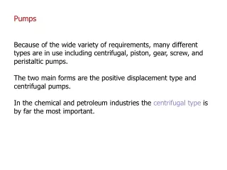
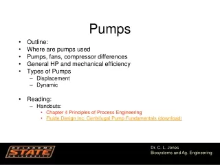
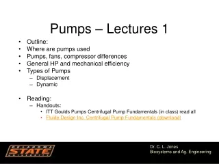
The PowerPoint covers key concepts, maintenance schedules, and troubleshooting steps. Below is the content layout, and I'll proceed to generate the actual PowerPoint file:<br><br>Slide Outline<br>Title Slide:<br><br>"Motor Pump Operation & Maintenance (O&M)"<br>Subtitle: Overview for Practical Training<br>Introduction:<br><br>Brief on household and micro-irrigation development.<br>Importance of motor pump O&M for sustainable use.<br>Motor Pump Technology:<br><br>Definition and functionality.<br>Key parts: driven and driving components.<br>Types of Pumps:<br><br>Kinetic energy pumps (centrifugal, turbine).<br>Positive displacement pumps (piston, p
E N D
Motor Pumps O & M practical Manual By Zeleke Belay Zelebelay70@gmail.com Ministry of agriculture 1
Contents Contents 1. 2. 3. 4. 5. Introduction ............................................................................................................................................................................ 3 what is motor pump technology............................................................................................................................................. 4 Type of motor pump technology and selection criteria ......................................................................................................... 4 Driving energy part- (Motor or engine) .................................................................................................................................. 5 Planning & design consideration on using motor pump technology .................................................................................... 16 5.1. SPECIFICATIONS (የሞተርዝርዝርክፍሎችመለያናማሳያ ) .................................................................................................................. 16 5.2. INSTALLATION ..................................................................................................................................................................... 17 5.3. POWER TRANSMISSION TO DRIVEN MACHINES ................................................................................................................. 18 5.4. CHECKS AND CORRECTIONS ............................................................................................................................................... 18 6. steps used to apply motor pump technology ....................................................................................................................... 19 6.1. GENERAL DESCRIPTION OF ENGINE COMPONENTS ጠቅላላየሞተር (የኢንጂን) ስምክፍሎች .................................................... 19 6.2. CARBURETOR ካርቡሬተር ................................................................................................................................................. 23 6.3. AIR CLEANER ኤርክሊነር (ደብራተር) ................................................................................................................................... 23 7. Operation & Maintenance /O&M /procedures of motor pump ........................................................................................... 26 7.1. Major problems on Engine operation................................................................................................................................. 26 8. DISASSEMBLY AND REASSEMBLY ኢንጂንመበተንናእንደገናመግጠም ............................................................................................... 27 8.1. PREPARATIONS AND SUGGESTIONS ............................................................................................................................ 27 8.2. SPECIAL TOOLS ............................................................................................................................................................. 27 8.3. DISASSEMBLY PROCEDURES ........................................................................................................................................ 28 8.4. REASSEMBLY PROCEDURES .......................................................................................................................................... 38 8.5. CARBURETOR ............................................................................................................................................................... 40 8.6. DISASSEMBLY AND REASSEMBLY ................................................................................................................................. 41 8.7. OIL LEVEL SENSOR (OPTION) .............................................................................................................................................. 43 8.7. RECOIL STARTER ........................................................................................................................................................... 44 9.1. STARTING DIFFICULTIES ............................................................................................................................................... 47 9.2. . INSUFFICIENT OUTPUT ............................................................................................................................................... 48 9.3. OVERHEAT .................................................................................................................................................................... 49 9.4. ROUGH IDLING ............................................................................................................................................................. 49 9.5. HIGH ENGINE OIL CONSUMPTION ............................................................................................................................... 49 9.6. HIGH FUEL CONSUMPTION .......................................................................................................................................... 50 9.7. DETONATION ............................................................................................................................................................... 50 10. Periodical Maintenance schedule .................................................................................................................................... 51 10.1. DAILY MAINTENANCE................................................................................................................................................... 51 10.2. INITIAL 20 HRS. MAINTENANCE ................................................................................................................................... 51 10.3. EVERY 50 HRS. (10 DAYS) MAINTENANCE .................................................................................................................... 51 10.4. EVERY 100-200 HRS. (MONTHLY) MAINTENANCE ....................................................................................................... 51 10.5. EVERY 500-600 HRS. MAINTENANCE ........................................................................................................................... 52 10.6. EVERY 1000 HRS. (YEARLY) MAINTENANCE ................................................................................................................. 52 10.7. ENGINE STORAGE ......................................................................................................................................................... 52 11. Reference Documents for Motor pump module: ............................................................................................................. 54 2
1.Introduction House hold and micro irrigation development (HHMI) is booming in considerable pace and becoming an attractive household level irrigation option with an increasing performance by the farmers to use small scale motorized pumps for lifting ground water. In view of this, the number of motorized irrigation pumps in use are increasing in quantity drastically especially in areas with high ground water potential for irrigated agriculture. To ensure the sustainable use of these pumps service the issue of pump operation and maintenance (O&M) is vital and requires skills and techniques. Motor pump O&M techniques require good understanding of the pump and the driving units the engine, the engine part is major cause of operational defect which is a base for a major challenge, therefore basic principles of engine O&M skills for operation and maintenance of the water lifting devices is crucial to understand and operate for effective management of HHMI development at rural areas. Based on the diagnostic survey conducted in the areas of ground water potential and Micro-Irrigation userfarmer’s experiences confirms that a major challenge on pump O&M need to be addressed and requires technical understanding and practical training to understand the full function of the system. Accordingly, this training module is designed using participatory, practical and experiential training facilitation approach (ERGA) to help and give opportunities to the trainees to exchange experiences addressing the local problem. Due to simplification and easy understanding of training materials translation is mixed into local language /Amharic/ to make it reference material and user friendly during the training as well as afterwards. This will be helpful the trainees to effectively participate, easily learn and develop awareness on appropriate technologies and skills on motor pump O&M services and applicable solutions related to motorized pump effective service. At the end of the training participants were able to: ✓Understand the basic parts of motorized water pumps so as to prioritize timely service ✓Clearly differentiate driving and driven parts. ✓Acquire skills to advise farmers on selecting recommended motorized irrigation pumps and provide technical support on pump trouble diagnosis and troubleshooting and irrigation pumps repair. ✓Describe different types of internal combustion engines and the different engine parts like: the power chain, the stationary parts, the auxiliary parts and accessories. ✓Describe major principles of engine operation and have a clear knowledge and skill on Classification of Internal Combustion (IC) Engines ✓Define major causes for pump troubles and troubleshooting of motor pumps and understand repair and service procedures Based on the above indicated objectives of the training this training material is expected to develop the skill of participants, technical staff and irrigation engineers, private sector M&O workshop and service providers. Accordingly all relevant stakeholders will be able to participate on the training in order to develop awareness, modify and diffuse appropriate technologies and skills on motor pump M&O services and applicable solutions related to motorized pump effective service. 3
2.what is motor pump technology Pumps are mechanical devices which convert mechanical energy supplied to them into hydraulic energy, thus lifting liquid from a lower level to a higher level. Pumps are also used to lift or transfer fluid to a height or location that allows users or processes to access it. Pumps are classified based on the energy imparted to the fluid as positive displacement or Kinetic energy Water pumps contain two main parts such as: Part one; Driven part (the Pumps) Part two; Driving part- (Motor or engine) Most irrigation pumps fall within the following two categories (Savva and Frenken, 2002) 1.2Kinetic pumps ➢This category includes pumps such as centrifugal pumps, vertical turbine pumps, submersible pumps and jet pumps. ➢Most of these pumps operate within a range of discharge and head where the discharge will vary as the head fluctuates. 1.3. Positive displacement pumps Are group of pumps whereby the fluid is displaced by mechanical devices such as pistons, plungers and screws. ➢These types of pumps operate at high heads, but relatively low discharge. ➢They are generally used in hydraulic systems and in a number of special applications. ➢Mono pumps, rope and washer pumps, and most of the manual pumps fall into this category. 3.Type of motor pump technology and selection criteria Pumps are classified based on the energy imparted to the fluid as positive displacement or Kinetic energy a)Positive displacement pumps move fluid by mechanically displacing fluid inside the pump Rotary and reciprocating pumps are the two categories b) Centrifugal Pump which imparts kinetic energy to the pumped fluid which is then further converted to pressure energy when it exits the pump casing. - horizontal 4
- Vertical turbine pump - submersible pumps all are working with the same principle The centrifugal pump creates an increase in pressure by transferring mechanical energy from the motor to the fluid through the rotating impeller. The energy changes occur by virtue of two main of the pump, the impeller and the volute or diffuser. The impeller is the rotating part that converts driver energy into the kinetic energy. The volute or diffuser is the stationary part that converts the kinetic energy into pressure energy. parts (Figure above depicts a side cross-section of a centrifugal pump indicating the movement of the liquid) The fluid flows from the inlet to the impeller center and out along its blades.As liquid leaves the eye of the impeller, a low-pressure area is created causing more liquid to flow toward the inlet. Because the impeller blades are curved, the fluid is pushed in a tangential and radial direction by the centrifugal force. The key idea is that the energy created by the centrifugal force is kinetic energy. This kinetic energy of a liquid coming out of an impeller is harnessed by creating a resistance to flow. The first resistance is created by the pump volute (casing) that catches the liquid and slows it down. In the discharge nozzle, the liquid further decelerates and its velocity is converted to pressure according to Bernoulli’s principle. 4.Driving energy part- (Motor or engine) Source of power for pumps is external to the pump. It can be Electrical motor or Engine. In this part, engines will be considered. Engines used in pumps are Internal combustion engines. As the name suggest, the combustion of fuels takes place in the cylinder of the engine. The heat is converted into useful power for different uses. Processes needed to run simple engine The following are needed to run a simple engine. ➢Air, fuel and combustion 5
➢Reciprocation and rotary motion ➢Compression of fuel air mixture ➢Engine cycle two or four stroke Air, fuel and combustion ➢These are the three elements needed to produce heat energy in the engine. ➢Air can be compressed-i.e. one cubic meter air can be packed into one cubic centimeter or less. ➢Air heats when it compressed. ➢Fuels must mix readily with air and easily ignite. The fuel (usually gasoline) used to power reciprocating engines is potential energy up to the moment it is mixed with air (oxygen) and burned. ➢Thus, when the piston in a cylinder moves inward and compresses the gas, the temperature of the gas increases. ➢Then the high temp vaporizes the fuel then each particle is mixed with air. ➢How much the temperature increases depend on how far the piston travels. The rate of burning depends on: a.How much the air is compressed and heated? b.How much fuel is used? c.How volatile the fuel is? Reciprocation and rotary motion The up-and-down movement of the piston is converted to rotary motion to turn the propeller by the connecting rod and the crankshaft. The four basic parts needed to make these two motions are ➢Cylinder ➢Piston ➢Connecting road and ➢Crankshaft The piston wall is grooved to accommodate rings which fit tightly against the cylinder wall and help seal the cylinder's open end so that gases cannot escape from the combustion chamber. The combustion chamber is the area between the top of the piston and the head of the cylinder when the piston is at its uppermost point of travel. Types of Engines Types of internal combustion engines (IC) Carburetor type IC engine: in this engine liquid fuel is atomized, vaporized and mixed with air in correct proportion before being taken into engine cylinder through the intake manifold. The ignition of the mixture is caused by an electric spark and is known as spark ignition. Diesel type IC engine: In these types, only liquid fuel is injected in the cylinder under high pressure and on contact with the heated air, the fuel and air ignites spontaneously. Engine parts 6
The internal combustion engine is composed of mutually constrained and related parts that converts the pressure generated by the cylinder into rotational motion at the fly wheel and coordinates the events within the engine. They are classified into the following classes. ➢The power chain: to receive, exert and transmit the motive forces ➢The stationary parts: to constrain and support the moving parts ➢The valve and valve operating parts ➢The auxiliary parts and accessories: to cool and lubricate the surfaces and provide fuel to the engine. Piston and valve i) The power chain: Piston: the first part to begin the movement to transmit power to the crank shaft, the pressure and energy released by combustion of the fuel. The piston performs the following function: ➢Provides the vacuum during the intake stroke ➢Compresses air prior to ignition ➢Receive force of expanding gases and pass it onto the connecting rod ➢Pushes out the exhaust gas Connecting rods: The pressure on the piston is transmitted through the piston pin to the connecting rod and finally to the crankshaft. ii) The stationary parts Cylinder blocks: cylinder blocks are cast with center webs to support the crank and camshaft. They have a passage in their walls for coolant and oil. Cylinders: is hollow tube which guides the piston and forms the combustion chamber together with the cylinder head and piston. It has smooth interior finish. Cylinders are the heart of the engine where combustion process takes place. There are two types of cylinder. ▪Cast- in- blocks ▪Individual castings ▪Cylinder head: the upper end of cylinder is closed by the cylinder head which is securely bolted to the engine blocks to make a tight fit between the engine blocks and the cylinder head. 7
▪Crank case: the crank shaft fully enclosed in an oil tight housing. The crankshaft rotates in a plain bearing shell in the crank case, held in a position by bearing caps. ▪Inlet manifold: attached to the side of the cylinder head and serves to conduct air fuel mixture into cylinder. ▪Exhaust manifold: attached to cylinder head and serves to conduct the burned gases away from the engine. iii) Valves and valve operating parts; Each cylinder has a minimum two valves. One is called inlet valve that allows the air fuel mixture into the cylinder and the exhaust valve that permits burned gas to escape. Cam shaft: are fitted into the engine blocks on the left hand side, above the crank shaft. The push rods are moved by special devices called cams. The rotating camshaft gives the lifting action for opening the valves. Timing gear: the gear at the front of the cam shaft has twice as many teeth as the crank shaft drives it. It revolves only as half as fast as the crank shaft gear. Valve tappets: the lifting action of cam is transmitted to the valve tappet which is free to move up and down on its guide. The tappet intern presses the lower end of the valve stem and pushes the valve to open. Push rod: push rod transfers the motion from tappet to the rocker arm. It is usually made of hollow steel pipe with solid steel end. Valve spring: the main function of the valve spring is to close the valve and keep it closed until it is forced open again by the camshaft. Rocker arm: the rocker arm transmits the cam shaft motion into the valve. Lubricating oil is pumped through a hollow shaft to lubricate all the rocker arm. Value guide: holds the valves centered for proper seating. It transfers heat from the valve stem to the cool valve. Classification of IC Engines There is no standard method of classifying internal combustion engines. They may be classified in many ways, such as according to the: ➢cylinder arrangement (In line, V-type, opposed) ➢working cycle employed (four stroke, two stroke) ➢fuel used (petrol, diesel LP engine) ➢number of cylinder (four cylinders, six cylinders) 8
➢nature of thermodynamic cycle (Otto, diesel cycle) ➢method of cooling (water cooled, air cooled) ➢field of application (stationary, automobile) ➢fuel injection (Spark ignition, compression ignition) ENGINE OPERATION SYSTEM Processes needed to run simple engine The following are needed to run a simple engine. ➢Air, fuel and combustion ➢Reciprocation motion and rotary ➢Compression of fuel air mixture ➢Engine cycle two or four stroke Air, fuel and combustion ➢These are the three elements needed to produce heat energy in the engine. ➢Air can be compressed-i.e. one cubic meter air can be packed into one cubic centimeter or less. ➢Air heats when it compressed. ➢Fuels must mix readily with air and easily ignite. The fuel (usually gasoline) used to power reciprocating engines is potential energy up to the moment it is mixed with air (oxygen) and burned. ➢Thus, when the piston in a cylinder moves inward and compresses the gas, the temperature of the gas increases. ➢Then the high temp vaporizes the fuel then each particle is mixed with air. ➢How much the temperature increases depend on how far the piston travels. 9
The rate of burning depends on: 1.How much the air is compressed and heated? 2.How much fuel is used? 3.How volatile the fuel is? Reciprocation and rotary motion The up-and-down movement of the piston is converted to rotary motion to turn the propeller by the connecting rod and the crankshaft. The four basic parts needed to make these two motions are ➢Cylinder ➢Piston ➢Connecting road and ➢Crankshaft The accommodate rings which fit tightly against the cylinder wall and help seal cylinder's open end so that gases cannot escape from the combustion chamber. piston wall is grooved to the The combustion chamber is the area between the top of the piston and the head of the cylinder when the piston is its uppermost point of travel. at Compression of fuel air mixture ➢As a general summary of Boyle's you should remember that a decrease in volume causes an increase in pressure. law, ➢An increase in volume causes a decrease in pressure. The internal combustion engine works best when the fuel air mixture is well compressed. 10
➢The fuel air is mixed by weight not by volume. The petrol engine mixes 10 gallons of petrol with about 90,000 gallons of air. The overall principles of reciprocating engine operation are easy to understand if you remember what happens with each stroke that the piston makes. Engine cycle two or four stroke Four stroke Engine cycles. As their name implies, four-stroke internal combustion engines have four basic steps that repeat with every two revolutions of the engine: 1. Intake stroke 2. Compression stroke 3. Power stroke and 4. Exhaust stroke l. Fuel system ➢The fuel system must deliver clean fuel, in the required quantity to the combustion chamber. ➢Spark ignition engines requires fuels with certain qualities, while the diesel engine requires other fuel qualities. ➢The most common fuel for internal combustion engine are diesel and petrol. Important qualities of petrol fuel for petrol engine a) Easy staring: ➢the petrol property which is most important in engine starting is volatility. Volatility or the ability to vaporize, is an important fuel property because liquids will not burn. ➢Petrol which vaporizes too readily may boil in fuel lines or carburetor and causes a decrease in fuel flow to the engine resulting in rough operation or stoppage. ➢And Petrol which does not vaporizes too readily may cause hard starting and poor warm up and acceleration as well as un equal distribution of fuel to the cylinders b) High oxidation stability and freedom from gum: 11
➢The tendency of the petrol to form gum in storage is an indication of its oxidation stability. Antioxidant additive that minimize gum formation are used to adequately stabilize most of today's petrol. ➢c) Freedom from foreign matter: Freedom from dirt and moisture is mostly a matter of how petrol is handled and stored. Important qualities of diesel fuel for diesel engine; ➢a) Volatility: the properties that affects burning. The volatile fuel will make the engine start better. The ocetane rating is the rating given to diesel fuels for their ability to burn without detonation. ➢b) Pour point: the lowest temperature to which the fuel ceases to flow is known as pour point. Diesel fuels flow at the lowest atmospheric temperature. Low pour point can be obtained only at the expense of the low octane number or high volatility. ➢c) Cloud point: the lowest temperature to which the fuel can be exposed before it begins to cloud or to form paraffin crystals. This is closely related to the pour point and becomes very important if you are attempting to operate engine during cold weather. The presence of solidified waxes thickens the oil and clogs fuel filters and injectors in engines. Therefore, cloud point indicates the tendency of the oil to plug filters or small orifices at cold operating temperatures. ➢d) Viscosity: generally known as resistance to flow. If the viscosity is too low or too high the injection system will not operate correctly. ➢e) Flash point: the flash point of diesel fuel is the temperatures to which the fuel must be heated before it will give off sufficient vapor to ignite. A lower flash point indicates higher flammability. Compression and fuel ➢The higher compression ratio, the more air-fuel mixture compressed and the higher the pressure inside the cylinder before the fuel burns. ➢compression ratio is the ratio of combustion chamber volume at BDC to that volume at TDC. The volume remaining above the piston head at TDC is referred to as the clearance volume. ➢CR = (displacement volume + clearance volume)/clearance volume ➢Diesel fuels require higher CR than petrol fuel ➢Higher CR engines may be expected to be more efficient than low CR engines. Petrol fuel system ➢The function of petrol fuel system is to supply the proper quantities of fuel and air, mix them and distribute them uniformly to each cylinder. 12
➢Fuel – air ratio requirements: The rapidity with which the fuel injection takes place in the engine makes it impossible to obtain perfect mixing of air and fuel, there must be an excess of one another. The petrol fuel system supplies a combustible mixture of fuel and air to power the engine. Basic parts of the petrol fuel system. ➢Fuel tank: store the petrol for the engine ➢Fuel filter: to clean the fuel before it enters the fuel pump. ➢Fuel pump: moves the fuels from the tank to the carburetor. ➢Fuel lines: generally made of steel tubing. The fuel lines simply transfer fuel from one location to another. ➢Carburetor: the petrol must be vaporized and mixed with air for all types of condition. The primary job of carburetor is to produce flammable fuel- air ratio for any type of operating condition Fuel is supplied to petrol fuel system in two ways: ❖Gravity feed system; gravity system has a fuel tank placed above the carburetor. This system maintains a uniform level in carburetor regardless of amount of fuel in tank. ❖Force feed system; the force feed system allows the fuel tank to be located at the level below the carburetor. Fuel filters: contamination of fuel is a major cause of excessive engine wear and failure. The purpose of separate filter is to trap water and any foreign objects that may contaminate the fuel system. Carburetor: ➢the petrol must be vaporized and mixed with air for all types of condition. ➢By mixing fuel with air, carburetor regulates the combustion and the power of the engine. ➢The primary job of carburetor is to produce flammable fuel- air ratio for any type of operating condition. Qualities of carburetor; ➢To supply rich fuel air mixture when engine is cold at the time of starting. ➢To correct the supply of fuels when engine gets heated up. ➢To supply correct quantity of fuel at idle speed. ➢To supply enough fuel when required. ➢Respond to sudden acceleration and supply rich mixture. 13
Theory of pressure differential -Venturi principle ➢A venturi is used in the throat or bore of all carburetors to create this pressure differential. ➢The faster the air moves the lower the air pressure at the venturi. ➢This low pressure is the basic force by which the carburetor works. ll. Cooling system Basic cooling system components ➢The primary components in a vehicle cooling system are: radiator, thermostat & housing, water pump, cooling fan, radiator hoses and heater hoses. ➢Radiator: ➢The radiator consists of top and bottom tanks, and a core. ➢The radiator core allows the coolant to pass through it in either a vertical down or horizontal cross flow direction. In addition, the radiator core serves as a good conductor of heat away from the engine. ➢The header tank, or reservoir, can be mounted separately from the radiator. It has a supply of coolant and is located higher than the top of the radiator. The reservoirs are usually made of hardened plastic, which allows for a visual checking of the fluid level through the plastic. The pressurized radiator cap is used to increase the boiling point of the coolant. It can be located directly on the top of the radiator or on the header (or surge) tank. Water pump The water pump is normally bolted to the front of the engine block. The bottom radiator hose comes from the radiator and is connected to the water pump inlet. The water pump is driven by the engine via a fan or drive belt. As the coolant leaves the outlet of the radiator, which has removed much of its heat, the water pump forces it through the water jackets by the action of the impeller in the pump. Cooling fan The cooling fan can be located on the water pump shaft, or it may be attached directly to the engine crankshaft. In most cases, this requires some engine power to drive the fan. The blades of the cooling fan can be made of steel or plastic. The blades draw cooling air through the radiator core, thus lowering the temperature of the coolant. lll. 3) Engine Lubrication system The lubrication system is designed to keep the components in the engine lubricated and to reduce friction. 14
a) Splash lubrication system: In the splash lubrication system, a dipper or slinger splashes oil through the internal parts of the engine. Oil is also splashed up to the valve mechanism. b) In force-feed lubrication: pressure forces oil around the engine. In a wet-sump system, oil is kept in the sump ready for the next use. In a dry sump system, oil falls to the bottom of the engine and a scavenge pump sends it to an oil tank. c) 2-stroke engine premix fuel system: Most 2-stroke gasoline engines use a set gasoline-oil mixture for lubrication. As the air, fuel and oil enter the crankcase, the fuel evaporates, leaving behind enough oil to keep parts coated and lubricated. Lubrication system components Sump: The sump is at the base of an engine. It can be used as a storage container in a 'wet sump system'. Oil collection pan: An oil collection pan is used in 'dry sump systems' prior to being returned to an oil tank. Oil tank: The oil tank is part of the dry sump lubrication system and is used for oil storage. Oil pump: Oil pumps deliver oil under pressure to the internal engine parts. In a rotor-type oil pump, an inner rotor drives an outer one. Pressure differences force the oil to move. Geared oil pumps use a similar principle. Oil filters: The oil filter helps to clean the oil in the system. If the filter clogs, a valve opens and directs unfiltered oil to the engine. Most oil-filters on diesel engines are larger than those on similar gasoline engines. Spurt holes & galleries: Spurt holes and galleries are used to deliver oil from the oil pump to various components and bearings in the engine. Oil pressure relief valve: The pressure relief valve is used to prevent damage to an engine due to too much oil pressure. Vl. Air filtration system: The objective of an engine air intake system is to eliminate solid particles from reaching the engine while still allowing sufficient air for efficient combustion of the fuel. 15
5.Planning & design consideration on using motor pump technology 5.1. SPECIFICATIONS (የሞተርዝርዝርክፍሎችመለያናማሳያ የሞተርዝርዝርክፍሎችመለያናማሳያ ) MODEL (ሞዴል) EY15-3D EY20-3D Air-Cooled (በአየርየሚቀዘቅዝ), 4-Cycle, Single-Cylinder (ነጠላሲሊንደር), Type ዓይነት Side Valve (የጎንቫልቭ), Gasoline Engine (የቤንዝንኢንጂን) Bore x Stroke የሲሊንደርስፋትእናምት 63 x 46 mm (2.48 x 1.81 in.) 67 x 52 mm (2.64 x 2.05 in.) 143 cm3 (8.73 cu.in.) 183 cm3 (11.17 cu.in.) Piston Displacement የፒስተንእንቅስቃሴ Compression Ratio የመታመቅንጽጽር 6.3 1.6 kW (2.2 HP) /3000 r.p.m. 2.2 kW (3.0 HP) /3000 r.p.m. Continuous 2.0 kW (2.7 HP) /3600 r.p.m. 2.6 kW (3.5 HP) /3600 r.p.m. Output ዉጤት Max. 2.6 kW (3.5 HP) /4000 r.p.m. 3.7 kW (5.0 HP) /4000 r.p.m. Max. Torque / ከፍተኛውሥክርክሪት/ 6.7 N・m (0.68 kgf・m) / 2800 r.p.m. 9.3 N・m (0.95 kgf・m) / 2800 r.p.m. Direction of Rotation የዙርአቅጣጫ Counterclockwise as viewed from P.T.O. shaft side Forced Air Coolingአዬርበመቅዘፍ Side Valve በጎንየተቀመጠቫልቭ Splash Type በመርጨት Automobile Oil SAE #20, #30 or 10W-30 ; Class SE or higher 0.6 liters (0.156 U.S. gal.) በሊትር Horizontal Draft,አግድምየተሰራ Float Type ተንሳፋፊዓይነት Automobile Unleaded Gasoline ያልተቀላቀለቤንዝል 380 g/kW・h (280 g/HP・h) at Continuous Rated Output Gravity Type በዘቅዛቃስበትዓይነት 2.8 liters (0.74 U.S. gal.) Flywheel Magneto (Solid State) በማግኔትፍጭትናመሳሳብ NGK B6HS Recoil Starter በገመድስበትናማዞርማስነሳት Centrifugal Flyweight Type በተሸከርካሪመዘውር 13.2 kg (29.1 lb.) 294 mm x 304 mm x 368 mm Cooling system የማቀዝቀዝስርዓት Valve Arrangement የቫልቭአቀማመጥ Lubrication የማለስለስሁኔታ Lubricant የቅባትዓይነት Capacity of Lubricant የቅባትመጠን Carburetor ካርቡሬተር Fuel የነዳጅዓይነት Fuel Consumption Ratio የነዳጅፍጆታ Fuel Feed System የነዳጅአሳሳብ Fuel Tank Capacity ነዳጅየመያዝመጠኑ 3.8 liters (1.00 U.S. gal.) Ignition System የማቀጣጠያስርዓት Spark Plug Starting System Governor System Dry Weight 15.0 kg (33.1 lb.) 303 mm x 318 mm x 392 mm Dimensions (L x W x H) (11.57 in. x 11.97 in. x 14.49 in.) (11.93 in. x 12.52 in. x 15.43 in.) NB. This is a sample, Specifications are subject to change without notice. 16
5.2. INSTALLATION Engine life, ease of maintenance and inspection, frequency of checks and repairs, and operating cost are all depend on the way in which the engine is installed. Review the following instructions carefully for installing the engine. INSTALLING When mounting the engine, carefully examine its position, the method of connecting it to a machine, the foundation, and the method of supporting the engine. When determining its mounting position, in particular, make sure that gasoline and oil can easily be supplied and checked, the spark plug can easily be checked, the air cleaner can easily be serviced, and that the oil can easily be discharged. VENTILATION Fresh air is necessary for cooling the engine and burning the fuel. In the case the engine is operated under a hood or in a small room, temperature rise in the engine room can cause vapor lock, oil deterioration, increased oil consumption, loss of power, piston seizure, shorter engine life, etc., making it impossible to operate the engine properly. It is necessary, therefore, to provide a duct or baffle to guide cooling air to the engine to prevent recirculation of he hot air used for engine cooling, and temperature rise of the machine. Keep the engine room temperature below 50°C even in the hottest period of the year. EXHAUST GAS DISCHARGE Exhaust gas is noxious. When operating the engine indoors, be sure to discharge the exhaust gas outdoors. If a long exhaust pipe is used in such a case, the internal resistance increases causing loss of engine power. Thus pipe inside diameter must be increased in proportion to exhaust pipe length. Exhaust pipe : Less than 3 m long, pipe inside diameter 30 mm, Less than 5 m long, pipe inside diameter 33 mm. NOTE:Fit safety covers to the exhaust pipe and to the muffler. FUEL SYSTEM If the fuel tank removed from the engine, set the height of the bottom of fuel tank and the fuel joint of carburetor to a level between 5 cm and 50 cm.Pay attention that the too low level of fuel tank allows fuel not to be supplied and the too high may cause the carburetor overflow. When piping, in addition, pay attention to the pipe for its heat transfer thickness, bend and leaking in joints to prevent air-lock and vapour-lock.And length of the pipe should be as short as possible. 17
5.3. POWER TRANSMISSION TO DRIVEN MACHINES BELT DRIVE Take the following notes into consideration. *V-belts are preferable to flat belts. *The driving shaft of the engine must be parallel to the driven shaft of the machine. *The driving pulley of the engine must be in line with the driven pulley of the machine. *Install the engine pulley as close to the engine as possible. *If possible, span the belt horizontally. *Disengage the load when starting the engine. If no clutch is used, use a belt tension pulley or the like. FLEXIBLE COUPLING When using a flexible coupling, runout and misalignment between the driven shaft and engine shaft must be minimized. Runout and misalignment tolerance are specified by the coupling manufacturer. 5.4. CHECKS AND CORRECTIONS After disassembling and cleaning the engine, check and repair, if necessary, according to the correction table. The correction table applies whenever the engines are repaired. It is important for the servicemen to be familiar with the contents of this table. Correct maintenance is recommended by observing the correction standards specified. The meanings of the terms used in the correction table are as follows: 1) Correction Repair, adjustment or replacement of any engine parts. 2) Correction Limit The limit on wear, damage or functional deterioration of engine parts beyond which normal engine performance cannot be expected without repairing such parts. 3) Use Limit The limit beyond which parts can no longer be used in respect of performance or strength. 4) Standard Dimensions The design dimensions of new parts minus tolerance. 5) Correction Tolerance Tolerance on the dimensions of engine parts refinished or adjusted. 18
6.steps used to apply motor pump technology 6.1.GENERAL DESCRIPTION OF ENGINE COMPONENTSጠቅላላየሞተር ጠቅላላየሞተር (የኢንጂን CYLINDER AND CRANKCASEሲሊንደርብሎክ ሲሊንደርብሎክ(ካምቻ The cylinder and crankcase are single piece alu-minum die-casting. ሲሊንደርብሎክእናክራንክኬዝወጥሆኖበአልሙኒዬምየተሰራነዉ፡፡ The cylinder liner, made of special cast iron, is molded into the aluminum casting. የኢንጂን) ስም ስምክፍሎች ክፍሎች ካምቻ) እናክራንክኬዝ እናክራንክኬዝ(ሶቶኮፓ ሶቶኮፓ) ሲሊንደርላይነርየሚንለዉየሚሰራዉከጠንካራየብረትምርትሲሆንየሚገባእናየሚወጣነዉጣሳይመስላል፡፡ The intake and exhaust ports are located on one side of the cylinder, and are also inserted into the casting. አሰገቢእናአሰወጪቫልቮላከሲሊንደሩጎንኢንጅንብሎኩዉስጥይገኛሉ፡፡ MAIN BEARING COVER ዋናዉኩቺኔታመሸፈኛክፍል The main bearing cover is an aluminum die-cast-ing, which is mounted on the output shaft የዋናዉኩቺኔታመሸፈኛየሚከድነዉየሻፍትመዉጫዉንነዉ፡፡ Remove the main bearing cover to inspect inside of the engine. የኩቺኔታመሸፈኛዉንበመፍታትየዉስጠኛዉንየኢንጂንክፍልማየትእንችላለን፡፡ Pilots and bosses are machined on the cover for direct mounting of the engine onto such machines side of the crankcase. as generators and pumps. ደጋፊብረቶችናቀዳዳዎችበኩቺኔታመሸፈኛላይስለተሰሩበቀጥታጄነረተርእናፓምፖሊታሰሩይችላሉ፡፡ Oil gauges (fillers) are on both sides of the cover for easy maintenance. የዘይትመለኪያበሁለቱምአቅጣጫበቀላሉማየትእንዲንችልተገጥሟል፡፡ CRANKSHAFT ክራንክሻፍት The crankshaft is forged carbon steel, and the crank pin is induction-hardened. The output end of the shaft has a crankshaft gear that is pressed into position. የክራንክሻፍቱጥርስ(ኮሎጥርስ) በምርትወቅትከኮሎዉጋርበግፊትእንዲገናኝተደርጎተመርቷል፡፡ ክራንክሻፍት(ኮሎ ኮሎ) 19
CONNECTING ROD AND PISTONኮኔክቲንግሮድ(ቤላ) እናፒስተን The connecting rod is forged of aluminum alloy, and its large and small ends fanction as bearings. The large end has a built-in oil scraper for splash-ing the lubricating oil. ቤላከአልሙኒየምዉሁድጠንካራእንዲሆንተደርጎየተሰራነዉ፡፡ትንሽቀ ዳዳበላይኛዉጫፍእናትልቅቀዳዳየሚከፈትበታችኛዉጫፍአሉት፡፡ሁ ለቱምቀዳዳዎችእንደኩቺኔታያገለግላሉ፡፡በትልቁጫፍዘይትእየጨለፈ የሚረጭክፍልአለዉ፡፡ The piston is an aluminum alloy casting, and car-ries two compression rings and one oil ring. ፒስተኑከአልሙኒየምዉሁድሶስትየፒስተንቀለበትእንዲይዝቦይተደርጎ በትየተሰራነዉ፡፡ሁለቱየላይኛዉቀለበቶችለማመቅየሚረዱሲሆንሶስተ ኛዉዘይትወደማቀጣጠያክፍልእንዳይገባመከላከያነዉ፡፡ Top Ring Second Ring Oil Ring Connecting Rod Oil Scraper Fig. 4-4 CAMSHAFTካምሻፍት The camshaft is made of special cast iron, and camshaft and gear are cast together in one piece. Both sides of the shaft fit into the plain bearings on ካምሻፍት(አልብሮካም አልብሮካም) the crankcase and main bearing cover. ካምሻፍቱጥሩከሆነካስትብረትየተሰራነዉ፡፡ካምሻፍቱናካምጥርሱበምርት ወቅትአንድላይካስትተደርጎነዉየሚመረተዉ፡፡ካምሻፍቱበአንድበኩልክራ ንክኬዝ(ሶቶኮፓ) በሌላበኩልደግሞበዋናኩቺኔታማቀፊያበልሙጥኩቺኔታታቅፎይቀመጣል ›፡፡ VALVE ARRANGEMENTቫልቭ ቫልቭ (ቫልቮላ The exhaust valve is located upstream of the cool-ing air with the result that the exhaust valve is intensively cooled for improved engine durability. ሁለቱምቫልቮላዎችከካምቻዉበአንድጎንሲሊንደርብሎኩዉስጥናቸዉ፡፡ጋዝየ ማስወጫዉቫልቮላመጠኑአነስያለሲሆንአቀማመጡምወደፍላይዊሉበኩልነዉ ፡፡የዚህምምክንያትበፍላይዊሉየሚገፋዉአየርበተሎእንዲያቀዘቅዘዉነዉ፡፡ Fig. 4-5 Exhaust Valve Intake Valve ቫልቮላ)አቀማመጥ አቀማመጥ Fig. 4-6 20
CYLINDER HEADሲሊንደርሄድ The cylinder head is an aluminum die-casting, and forms a Ricardo type combustion chamber with squish area for high combustion efficiency. The spark plug is tilted for easy mounting of the fuel tank. ሲሊንደርሄድ(ቴስታታ) የተሰራዉከአልሙኒየምሆኖለጥሩየጋዝመቀጣጠልያመች ሲሊንደርሄድ(ቴስታታ ቴስታታ) ዘንድየተለየየንድፍስራየተሰራለትነዉ፡፡ከዚህምበተጨማሪየነዳጅሳልባቲዮየሚቀ መጥበትንለማመቻቸትሲባልየካንዴላማስገቢያውገደልያለነዉ፡፡ GOVERNOR SYSTEM (የገበርነርስርአት የገበርነርስርአት) The governor is a centrifugal flyweight type which ensures constant operation at the selected speed during load variations. The governor gear with governor weights is in-stalled on the main bearing cover. ገቨርነሩዋናስራየኢንጂኑንፍጥነትበተለያየየኢንጂንሸክምወቅትየተመጣጠነ ማድረግነዉ፡፡አሰራሩምበገቨርነሩሽክርክሪትየሚዘረጋናየሚታጠፈዉየገቨርነር አካልየካርቡሬተሩንቾክእንዲቆጣጠረዉበማድረግነዉ፡፡የገቨርነርጥርስናተለጣጩ Main Bearing Cover የገቨርነርአካልየሚቀመጡትበዋናኩቺኔታአቃፊዉስጥነዉ፡፡ COOLING SYSTEM Y የማቀዝቀዝስርአት የማቀዝቀዝስርአት The large fins on the flywheel provide sufficient cooling air capacity for the cylinder and cylinder head. The cylinder baffle and head cover are provided for guiding the cooling air. Fig. 4-7 ካምቻእናቴስታታዉየሚቀዘቅዘዉበፍላይዊሉበሚገፋዉአየርአማካኝነትነዉ፡፡በቀላሉአየሩወደእነዚህክፍ ሎችእንዲደረስመንገዶችተዘጋጅተዋል፡፡ LUBRICATION SYSTEMበቅባትየማለስለስስርአት All the rotating and sliding parts are splash- lubricated by the oil scraper on the connecting rod. የሚሽከረከሩናየሚንሸራተቱየኢንጂኑክፍሎችበቅባትየሚለሰልሱትበቅባት ጨላፊዉክፍልበሚረጨዉቅባትነዉ፡፡ይህቅባትጨላፊየቤላትልቁቀዳዳአካል ነዉ፡፡ በቅባትየማለስለስስርአት 21
IGNITION SYSTEMየማቀጣጠያስርአት The ignition system is a transistor controlled mag-neto system which consists of a flywheel Ignition Coil Flywheel and an ignition coil with a built-in transistor mounted on the crankcase. የማቀጣጠያስርአቱበትራንዚስተርየሚታዘዝነዉ፡፡ስርአቱምበፍላይዊልላ ይበተገጠመማግኔት፣ክራንክኬዝላይበታሰረኢግኒሽንኮይል፣ካንዴላናሌሎ ችን ጥቃቅንቁሶችየያዘነዉ፡፡ የማቀጣጠያስርአት 6.2.CARBURETORካርቡሬተር ካርቡሬተር The engine is equipped with a horizontal draft car- buretor that has a float controlled fuel system and a fixed main jet. The carburetors are calibrated carefully for sure starting, good acceleration, less fuel consumption and sufficient output. For details, refer to page 30, section “7 CARBU- RETOR”. ካርቡሬተርነዳጁንበመመጠንወደመቀጣጠያክፍልየሚልክነዉ፡፡ ይህካርቡሬተርአግድምየአየርመግቢያእናተንሳፋፊየነዳጅመቆጣጠሪያቁስ አለዉ፡፡ካርቡሬተርበጣምጥንቃቄየሚጠይቅክፍልነዉ፡፡ልምድያላቸዉ ሙያተኞችሲያስተካክሉትኢንጂኑበቀላሉእንዲነሳ፣ትንሽነዳጅእንዲረጭ፣ጥሩ ጉልበትናፍጥነትእንዲኖረዉአድርገዉነዉ፡፡ Fig. 4-11 6.3.AIR CLEANERኤርክሊነር (ደብራተር) The air cleaner of the standard engine is an ob-long type using an urethane foam(semi-wet). As optional parts, dual-element type and cyclone chimney type is available. ይህየአየርማጽጃክፍልከፊልእርጥብነዉ፡፡ STD type Dual-element type (Option) Cyclone chimney type (Option) Fig. 4-12 23
SECTIONAL VIEW OF ENGINE Fuel Tank Spark Plug Cap Cylinder Head Spark Plug Ignition Coil Piston Pin Piston Recoil Starter Piston Ring Crankshaft Main Bearing Cover Flywheel Blower Housing Fig. 4-13 24
Speed Control Lever Air Cleaner Stop Switch Connecting Rod Carburetor Intake and Exhaust Valve Muffler Tappet Crankcase Camshaft Oil Scraper Fig. 4-14 25
7.Operation & Maintenance /O&M /procedures of motor pump 7.1. Major problems on Engine operation Engine will turn over but it won't start Three fundamental things can happen: a bad fuel mix, lack of compression or lack of spark. a) Bad fuel mix A bad fuel mix can occur in several ways: ➢You are out of gas, so the engine is getting air but no fuel. ➢ The air intake might be clogged, so there is fuel but not enough air. ➢The fuel system might be supplying too much or too little fuel to the mix, meaning that combustion does not occur properly. ➢There might be an impurity in the fuel (like water in your gas tank) that makes the fuel not burn. b) Lack of compression ➢If the charge of air and fuel cannot be compressed properly, the combustion process will not work like it should. Lack of compression might occur for these reasons: ➢Your piston rings are worn (allowing air/fuel to leak past the piston during compression). ➢The intake or exhaust valves are not sealing properly, again allowing a leak during compression. ➢There is a hole in the cylinder. ➢The most common "hole" in a cylinder occurs where the top of the cylinder (holding the valves and spark plug and also known as the cylinder head) attaches to the cylinder itself. Generally, the cylinder and the cylinder head bolt together with a thin gasket pressed between them to ensure a good seal. If the gasket breaks down, small holes develop between the cylinder and the cylinder head, and these holes cause leaks. c) Lack of spark The spark might be nonexistent or weak for a number of reasons: ➢If your spark plug or the wire leading to it is worn out, the spark will be weak; ➢If the wire is cut or missing, or if the system that sends a spark down the wire is not working properly, there will be no spark; and ➢If the spark occurs either too early or too late in the cycle (i.e. if the ignition timing is off), the fuel will not ignite at the right time, and this can cause all sorts of problem. d) Other things might be going wrong. For example: ➢ If the battery is dead, you cannot turn over the engine to start it; ➢ If the bearings that allow the crankshaft to turn freely are worn out, the crankshaft cannot turn so the engine cannot run; ➢ If the valves do not open and close at the right time or at all, air cannot get in and exhaust cannot get out, so the engine cannot run; ➢If someone sticks a potato up your tailpipe, exhaust cannot exit the cylinder so the engine will not run; ➢If you run out of oil, the piston cannot move up and down freely in the cylinder, and the engine will seize; and ➢In a properly running engine, all of these factors are within tolerance 26
8.DISASSEMBLY AND REASSEMBLYኢንጂንመበተንናእንደገናመግጠም 8.1. PREPARATIONS AND SUGGESTIONSዝግጅትእናእቅድ 1)When disassembling the engine, memorize the locations of individual parts so that they can be reassembled correctly. If you are uncertain of identifying some parts, it is suggested that tags be attached to them. ኢንጂንንስትፈታታእቃዎችንየፈታህበትንቦታበደንብለይተህእወቅ፣ይህመልሰህበምትገጥምበትጊዜበቀላሉናበትክክልእቃዉንቦታዉማሰርያ ስችልሃል፡፡የምትቸገርከሆነእቃዉላይምልክትእሰርበትወይምአድርግበት 2)Have boxes ready to keep disassembled parts by group. የአንድንክፍልየተፈቱቁሶችአንድላይአኑር 3)To prevent losing and misplacing, temporarily assemble each group of disassembled parts. ሊጠፋ፣ሊበተንወይምሊቀላቀልይችላልብለህየምታስበዉንየኢንጂንክፍልለጊዜዉእየገጠምህአስቀምጥ 4)Carefully handle disassembled parts, and clean them with washing oil if necessary. የተፈቱትንክፍሎችበትክክለኛዉየማጽጃቅባትበማጽዳትበጥንቃቄአስቀምጥ 5)Use the correct tools in the correct way. ትክክለኛመሳሪያእናትክክለኛዉንየአሰራርቅደምተከተልተጠቀም ኢንጂንመበተንናእንደገናመግጠም ዝግጅትእናእቅድ 8.2.SPECIAL TOOLS Part No. Tool Use Applicable Model EY10,13,14 Shape For mounting 227-95003-07 Valve Spring Retainer Valve Spring Retainer and Retainer Lock EY15,18,20 EY23,25,27 EY28 Fig.5-1 Fig.5- 2 227-95001-07 Valve Guide Puller For pulling off Valve Guide EY15,20 27
8.3. DISASSEMBLY PROCEDURESኢንጂንየመፍታትየአሰራርቅደምተከተል ኢንጂንየመፍታትየአሰራርቅደምተከተል Step Parts to remove Procedures Remarks Tool (1)Drain engine oil. Drain plugs on both sides of the crankcase. M14x12 Bolt ሁለቱንየዘይትማፍሰሻዎችበመፍታትየኢንጂኑ ንዘይትአፍስስ (1) Remove recoil starter. M6 x 8 Flange bolt: 4pcs. የገመድማስነሻዉንክፍልፍታ 1 Drain Plug የዘይትማፍሰሻ Be careful not to lose the gasket. ፍሳሽመከላከያዉእንዳ ይጠፋተጠንቀቅ 14mm Box spanner 2 Recoil Starter የገመድማስነሻክፍል 10mm Box spanner M6 x 8 Flange bolt : 4 pcs. STEP 2 Recoil Starter Gasket Drain Plug STEP 1 Crankcase Fig. 5-3 28
Step 3 Parts to remove Procedures Remarks Tool (1 10mm Box spanner Blower Housing አየርየሚዘዋወርበትክፍል Remove the blower housing from the crankcase and the cylinder head. M6 x 12 Flange bolt : 2 pcs. M6 x 14 Flange bolt : 2 pcs. አየርየሚዘዋወርበትንክፍልከሶቶኮፓዉ እናከቴስታታዉለይ Blower housing is fastened together with the fuel tank. አየርየሚዘዋወርበትክፍልከሰል ባትዮዉጋርየታሰረነዉ ) 4 10mm Box spanner or 10mm Spanner Fuel Tank and Head Cover ሳልባቲዮእናየቴስታታሽፋን (1 Close the fuel cock. የሳልበቲዮዉንየነዳጅመዉጫዝጋ Disconnect the fuel pipe between the fuel strainer and carburetor from the fuel strainer. ካርቡሬተርናየነዳጅማጣሪያዉንየሚአገ ናኘዉንቱቦበማጣሪያዉበኩልፍታ Remove the fuel tank from the cylinder head. M6 Nut : 2 pcs. ሳልባቲዩዉንከቴስታታዉፍታ Remove the head cover from the cylinder head. የቴስታታዉንሽፋንከቴስታታዉፍታ ) (2 ) (3 ) (4 ) 5 10mm Box spanner Air Cleaner የአየርማጣሪያ (1 Remove the air cleaner cover and element.የአየርማጣሪያዉንሽፋንእና ማጣሪያዉንቁስፍታ Remove the air cleaner case from the carburetor. M6 Nut : 2 pcs. የአየርማጣሪዉንየጀርባሽፋንከካርቡራ ቶሩለየዉ Disconnect the breather pipe. እስካሪኮዉንለይ Air cleaner case is fastened together with the carburetor. የአየርማጣሪያየጀርባሽፋንከካርቡ ራቶሩጋርየታሰረነዉ ) (2 ) (3 ) 6 10mm Box spanner Muffler Cover የጭስማዉጫሽፋን (1 Remove the muffler cover from the muffler. የጭስማዉጫሽፋንንከጭስማዉጫዉ ለይ M6 x 8 Flange bolt : 3 pcs. Remove the muffler from the cylinder portion of the crankcase. የጭስማዉጫዉንከካምቻውዘንድካለ ዉሶቶኮፓለይ M8 Nut : 2 pcs. ) 7 Muffler የጭስማዉጫ (1 12mm Spanner ) 29
Tool 10mm Box spanner or 10mm Spanner Step 8 Parts to remove Procedures Remarks Just loosen the bolt, unnecessary to take out the bolt. ዳዶዉንማላላትእንጂ ማዉለቅአያስፈልግም Governor Lever and the relative Parts የገበርነርመፈንቅልእናሌ ሎችተዘማጅክፍሎች (1) Loosen the bolt and remove the governor lever from the governor shaft. ዳዶዉንበማላላትየገበርነሩንመፈንቅልከገበ ርነሩሻፍትለይ M6 x 25 Bolt : 1 pc. (2) Remove the governor rod and rod spring from the carburetor. የገበርነሩንዘንግእናየዘንግእስፕሪንግከካርቡ ሬተሩለይ (1) Remove the carburetor from the cylinder portion of the crankcase. ካረቡሬተሩንወደካምቻበኩልካለዉሶቶኮፓ ለይ Carburetor ካርቡሬተር 9 STEP 9 31
Governor Spring Governor Rod Carburetor Governor Lever Bolt 32
StepParts to remove Ignition Coil የማቀጣጠያኮይል 10 Procedures Remarks Tool (1) Remove the spark plug cap from the spark plug , and remove the ignition coil from the crankcase. የካንዴላመሸፈኛዉንከካንዴላዉካነሳ ህበኋላየማቀጣጠያዉንኮይልከሶቶኮ ፓአንሳ M6 x 25 Bolt : 2 pcs. Sems bolt 10mm Box spanner Starting Pulley የማስነሻፑሊ (1) Remove the starting pulley from the flywheel.የማስነሻዉንፑሊከፍላይ ዊሉለይ M14 Nut : 1 pc. Fit a box or socket wrench over the flywheel nut, and strike it hard with a hammer to remove the nut (14mm) and spring washer.የፍላይዊሉንዳዶለማላላት ዳዶዉንበሬንችያዝናሬንቹንበፕላስቲ ክመዶሻወደግራደብድብከዚያምዳዶ ዉንወደሚፈታበትአቅጣጫፍታ 19mm Box spanner or Socket wrench Be careful not to damage the blades of the flywheel with a driver and a like. Strike counterclockwise with a hammer . ፍላይዊልላይያለዉየአየርመቅዘ ፊያእንዳይሰባበርጥንቃቄማድረ ግአለብን 11 Flywheel ፍላይዊል (1) Temporally assemble the fixing nut to the crankshaft thread until the end face. ዳዶዉንለጊዜዉኮሎዉላይሙሉበሙ ሉእሰረዉ (2) Tap the fixing nut with a Plastic hammer to remove the flywheel. ያሰርከዉንዳዶበፕላስቲክመዶሻእየመ ታህፍላይዊሉእንዲወጣአድርግ (1) Do not tap directly with a steel hammer. (2) Be careful not to damage the thread portion when using a steel hammer.የብረትመዶሻተጠቅመህየ ኮሎዉንጥርስእንዳትጎዳ 12 Tap the fixing nut after inserting aluminum bar between the fixing nut and a steel hammer. 33
Step Parts to remove Procedures Remarks Tool 17 Camshaft ኮሎ (1 Remove the camshaft from the crankcase. ኮሎዉንከሶቶኮፓዉአዉጣዉ To prevent the tappets from falling or damaging, put the crankcase to the flywheel side down. ታፔቱእንዳይወድቅወይምእንዳይጎዳ ኢንጂኑንበፍላይዊሉበኩልአስተኛዉ Before removing, put a mark of intake or exhaust on each tappet. የጋዝማስገቢያናማስዎጫታፔቱንለማ ለየትምልክትአድርግበት ) 18 Tappet ታፔት (1 Remove the tappets from the crankcase. ) Step Parts to remove Procedures ታፔቱንከሶቶኮፓአዉጣዉ Remarks Tool Spark Plug ካንዴለ (1) Remove the spark plug from the cylinder head. ካንዴላዉንከቴስታታዉለይ 21mm Box spanner 13 Cylinder Head (1) Remove the 8mm bolt and remove the cylinder head from the crankcase. ብሎኖችንበመፍታትቴስታታዉንከሶቶኮ ፓለይ M8 x 40 Bolt : 8 pcs. (2) Remove the cylinder head gasket from the crankcase.የቴስታታዉንክፍተትመድፈ ኛከሶቶኮፓለይ (1) Remove the tappet cover and the breather plate from the crankcase. የታፔቱንእናየእስካሪኮዉንሽፋንከሶቶከፓ ዉለይ M6 x 12 Bolt : 2 pcs. (2) Push in the intake and exhaust valve. ሁለቱንቫልቮላዎችግፋናተጫን (3) Remove the valve spring and the valve retainer. የቫልቮላዉንስፕሪንግእናእስፕሪንግመጠበ ቂያዉንአለያየ (1) Remove the fixing bolt of the main bearing cover from the crank case. የዋናኩቺኔታሽፋንንከሶቶኮፓጋርየአያያዘዉንብ ሎንፍታ M6 x 30 Bolt : 8 pcs. (2)Remove the cover, lightly tapping the cover evenly with a plastic hammer. በፕላስቲክመዶሻሽፋኑንበትንሹዙሪያዉንበመደ ብደብአለያየዉ 12mm Box spanner ቴስታታ 14 Intake and Exhaust Valve የጋዝማስገቢያናማስወ ጫቫልቮላ Put the notch on the outer circumference of the spring retainer on this side. Hook the medium size (-) driver at the dent (lower side) of the spring retainer and pull out the valves, while pulling the spring retainer toward you. 15 10mm Box spanner The front is this side. (-) Driver Main Bearing Cover የዋናኩቺኔታሽፋን 16 Be careful not to damage the oil seal. ቅባትከኢንጂኑእንዳይንጠባጠብ መከላከያዉንእንዳትጎዳተጠንቀ ቅ 10mm Box spanner 34
Exhaust Valve Intake Valve Valve Spring Spring Retainer Tappet Camshaft STEP 18 STEP 17 Camshaft Tappet Governor Gear Fig. 5-13 Fig. 5-12 35
(1) Scrape off carbon and other foreign deposits from the upper parts of the cylinder and piston, and then remove two pieces of connecting rod bolt. ከካምቻየላይኛዉክፍልናከፒስተኑላይየሚጋገረዉን ጥላሸትአጽድተህሁለቱንየቤላብሎኖችፍታ (2) Remove the oil scraper and connecting rod cap from the crankshaft. የዘይትመጨለፊያዉንእናየቤላማሰሪያዉንከኮሎዉ አላቀዉ (3) Turn the crankshaft until the piston comes to top dead center,and push out connecting rod and piston assembly from the top of cylinder. ፒስተኑንእናቤላዉንማዉጣትየሚቻለዉኮሎዉንበ ማሽከርከርፒስተኑላይኛዉጫፍሲደርስነዉ Piston and Ring ፒስተንእናየፒስተንቀለበት (1) piston pin, and take the piston off from the small end of the connecting rod. ሁለቱንየብረትማገጃዎችአዉጣእናየፒስተንቅርቃር አዉጥተህቤላዉንከፒስተኑለይ (2) Spread the open ends of the piston rings and remove them from the piston. ፒስተንቀለበቱላይያለዉንክፍተትበማስፋትበየተራ ፒስተንቀለበቱንከፒስተኑአዉልቅ Crankshaft ኮሎ (1) Remove the woodruff key (for the magneto). በኮሎዉጫፍበፍላይዊሉበኩልያለዉንየብረትቅር ቃርከጉድጓዱአዉጣ Step Parts to remove Connecting Rod and Piston ቤላእናፒስተን Procedures Remarks Tool 10mm Box spanner or 10mm Spanner 19 Remove the two clips, pull out the Be careful not to break the rings by spreading too much. ፒስተንቀለበቱንስታወልቅቀ ለበቱእንዳይሰበርበጣምአት ለጥጠዉ Be careful not to damage the oil seal. ዘይትእንዳይንጠባጠብመከ ላከያዉንእንዳትጎዳተጠንቀ ቅ 20 21 crankshaft with a soft hammer to remove it from crankcase. በፕላስቲክመዶሻበፍላይዊሉበኩልየኮሎዉንጫፍእ የመታህከሶቶኮፓዉአላቀዉ (2) Tap lightly on the flywheel end of 36
STEP 20 Clip Piston Ring Piston Piston Pin STEP 19 Woodruff Key Connecting Rod STEP 21 Crankshaft Oil scraper Fig. 5-14 Connecting Rod Bolt : 2 pcs. 37
8.4. REASSEMBLY PROCEDURESኢንጂንእንደገናየመግጠምስራየአሰራርቅደምተከተል ኢንጂንእንደገናየመግጠምስራየአሰራርቅደምተከተል ●PRECAUTIONS FOR REASSEMBLY እንደገናለመግጠምሚአስፈልጉጥንቃቄዎች እንደገናለመግጠምሚአስፈልጉጥንቃቄዎች 1)Clean parts thoroughly before reassembly. Pay most attention to cleanliness of piston, cylinder, crankshaft, connecting rod and bearings. የኢንጂንክፍሎችንበሚገባአጽዳ፣በተለይለፒስተን፣ለካምቻ፣ኮሎ፣ቤላእናኩቺኔታትኩረትስጥ፡፡ 2)Scrape off all carbon deposits from cylinder head, piston top and piston ring grooves. የተጠራቀመዉንከሰልከቴስታታ፣ከፒስተንአናትእናከፒስተንቀለበትማስቀመጫቦይፈቅፍቀህአንሳ 3)Check lip of oil seals. Replace oil seal if the lip is damaged. Apply oil to the lip before reassembly. የዘይትማገጃዉንቁስጠርዝእንዳይጎዳተጠንቀቅ፡፡እንደገናስትገጥምጠርዙንዘይትቀባ 4)If the gasket is stuck on the mounting surface, remove it carefully by taking care not to damage the surface. የክፍተትመድፈኛዉቁስከተጣበቀቀስብለህአስለቅቀዉ፤የተጣበቀበትንክፍልበማይጎዳመልኩ 5)Replace all the gaskets with new ones. አስፈላጊከሆነየክፍተትመድፈኛዉንቀይር 6)Replace keys, pins, bolts, nuts, etc., if necessary. አስፈላጊከሆነቅርቃሩን፣ብሎኑንእናዳዶዉንቀይር 7)Torque bolts and nuts to specification refer to the "TORQUE SPECIFICATIONS" (See page 56). 8)Apply oil to rotating and sliding portions. የሚሽከረከሩናየሚንሸራተቱየኢንጂንክፍሎችዘይትቀባ 9)Check manual.በዚህዶክመንትዉስጥየተጠቀሱትንየክፍተትእናየንቅናቄልኬቶችአስተካክል and adjust clearances and end plays where specified in this 10)When the main parts are assembled, check the movement and sound by rotating it manually. ዋናዋናየኢንጂንክፍሎችሲገጠሙእንቅስቃሴአቸዉንእናድምጹንበእጅእያሽከረከርህተመልከት CRANKSHAFT ኮሎ Polyvinyl tape Crankshaft Fig. 5-15 Open End of Piston Ring ኮሎ (1)Insert crankshaft in ball bearing of crankcase wrapping the key-way with polyvinyl tape to avoid damage to oil ላስትሮኮሎዉጫፍላይጠቅልለህኮሎዉንሶቶኮ ፓዉዉስጥባለዉኩቺኔታአስገባ seal. (2)Install woodruff key for flywheel on crankshaft. የፍላይዊሉንማገጃቅርቃርኮሎዉቀዳዳዉስጥአስተካክለህአስቀምጥ PISTON AND PISTON RINGS ፒስተንእናየፒስተንቀለበት 1)If no ring expander is available, install the ring by placing the open end over the first land of the piston, and spreading the ring only far enough to slip it over the correct ring groove. NOTE : Pay attention not to break the rings by twisting. Install the oil ring first followed by the second ring and ፒስተንእናየፒስተንቀለበት 38
BRAKE-IN OPERATION OF REASSEMBLED ENGINE An overhauled engine must be operated at low speed to break-in the parts. A thorough break-in is indis-pensable particularly when the cylinder, piston, piston rings or valves are replaced with new ones. The recommended break-in schedule is shown below. ኢንጂኑንከገጠምህበኋላበሰንጠረዡበተገለጸዉመሰረትፈትሸዉ፡፡ Petroleum Engines Petroleum Engines Petroleum Engines Petroleum Engines Step Load Engine Speed Time No Load No Load No Load Step 1 2,500rpm 10min. Step 2 3,000rpm 10min. Step 3 3,600rpm 10min. 1.0kW(1.35HP) Step 4 3,600rpm 30min. 1.3kW(1.75HP) 2.0kW(2.7HP) Step 5 3,600rpm 60min. 2.6kW(3.5HP) Table. 3 39
8.5.CARBURETOR OPERATION AND CONSTRUCTION (See Fig.7-1) FLOAT SYSTEM The float chamber is located just below the carburetor body, and the float (F) and the float valve (F.V) maintain a constant fuel level during engine operation. The fuel flows from the fuel tank into the float chamber through the float valve. When the fuel rises to a specific level, the float (F) rises; and when its buoyancy and fuel pressure are balanced, the float valve (F.V) close to shut off the fuel, thereby keeping the fuel at the reference level. Slow Air Bleed (S.A.B) Slow Port (S.P) Main Air Bleed (M.A.B) Choke (C) Throttle Valve (T.H.V) Main Nozzle (M.N) Idle Port (I.P) Slow Jet (S.J) 燃Fuel料 Float Valve (F.V) Float (F) Main Jet (M.J) Fig. 7-1 40
SLOW SYSTEM The pilot system feeds the fuel to the engine during idling and low-speed operation. The fuel is fed through the main jet (M.J) to the slow jet (S.J), where it is metered, and mixed with the air metered by the slow air bleed (S.A.B). The fuel-air mixture is fed to the engine through the idle port (I.P) and slow port(S.P). During engine idling, the fuel is mainly fed from the idle port (I.P). MAIN SYSTEM The main system feeds the fuel to the engine during medium and high-speed operation. The fuel is metered by the main jet (M.J) and fed to the main nozzle (M.N). The air metered by the main air bleed (M.A.B) is mixed with the fuel through the bleed holes in the main nozzle (M.N), and the mixture is atomized out of the main bore. It is mixed again with the air taken through the air cleaner into an optimum fuel-air mixture, which is supplied to the engine. CHOKE The choke (C) is used for easy start in the cold season. When the recoil starter is pulled with a closed choke (C), the negative pressure applied to the main nozzle increases and draws much fuel accordingly; thus easily start up the engine. 8.6.DISASSEMBLY AND REASSEMBLY (See Fig.7-2) Apart from mechanical failures, most of carburetor troubles are caused by an incorrect mixing ratio, which may arise mainly due to a clogged up air or fuel passage in jets, or fuel level variations. In order to assure proper flow of air and fuel, the carburetor must be kept clean at all times. The carburetor disas-sembly and reassembly procedures are as follows. THROTTLE SYSTEM (1)Remove the Philips screw (-2) and throttle valve (- 1), and pull out the throttle shaft (-11). When reassemble the throttle valve, apply a screw-lock agent to philips screw and tighten it with a tightening torque of 0.39~1.47 N・m (4~15 kg・cm) (0.3~1.1ft・lb). (2) The spring (-41) can be taken out by removing -8 -2 -1 -11 -32 -4 -3 - 61 -41 -40 -15 -14 -18 -19 -16 -5 the throttle stop screw (-40). *Exercise care not to damage throttle valve edge. CHOKE SYSTEM (1) Remove the clip (-4) and choke valve (-3), and pull out the choke shaft (-8). -22 (2) When mounting the choke valve, mark sure that the cutout of the choke valve locates on the right side when viewed from the outside. -17 -12 Fig. 7-2 41
SLOW SYSTEM (1)Remove the slow jet (-5), using correct tool to avoid damage to it. (2)When fitting the slow jet, screw it in fully and turn it back, accurately by the rotation specified in the table of correction standards. MAIN SYSTEM (1)Remove the bolt (-12) and take out float chamber body (-16). (2)Remove the main jet (-22) from the body. (3)Fasten the main jet securely to the body. Otherwise, the fuel may become too rich and cause engine malfunction. Main jet Tightening torque 0.98-2.94N・m (10-30kg・cm) (0.7-2.1ft・lb) (4) Bolt(-12) Tightening torque 7.85-11.77N・m (80-120kg・cm) (5.8-8.7ft・lb) FLOAT SYSTEM (1) Pull out the float pin (-15) and remove the float (-19) and float valve (-14). CAUTION: When cleaning the jets, use neither a drill nor a wire (because of possible damage of the orifice which will adversely affect fuel flow). Be sure to use compressed air to blow them clean. NOTE ; Check that the gasket (float chamber) is correctly fitted before mounting the float cham- ber body. 42
8.7. OIL LEVEL SENSOR (OPTION) FUNCTION When the oil level sensor detects the insufficient level of engine oil, it halts engine for warning and protection of engine. PRINCIPLE (1)Though it is very little, engine oil has electrical conductivity, while air is completely nonconductive. Utilizing this difference, presence of oil is identified by the current between electrodes of the sensor. (2)On the basis of this principle the sensing elements are merely fixed electrodes without mobile part, hence, it is possible to conduct reliable measurement without influence of vibration. And it is also shockresistant and free of deterioration. Outer electrode Inner electrode In case of no oil Conduction Fig. 9-1 43
8.7.RECOIL STARTER RECOIL STARTER (STEEL) Tools to be prepared: Driver, Pinchers (Pliers) and Protective Glasses WARNING Before starting the disassembly, make sure to wear the protective glasses. DISASSEMBLY STEPS (1) Relieve the spring power wise about a quarter circle for several times until it moves smoothly. -1: Hold the starter knob and extract the starter rope. -2: Extract the rope fully and hold the rope so that the knot of the rope in the reel makes a straight line with the rope guide. Fig. 10-1 -3: Hold the reel with the thumbs of both hands firmly so that the rope will not be wound back. (Fig.10-1) -4: Pull out the knot of the rope out of the reel, and unfasten the knot and pull it out toward the starter knob. (2 people required) -5: By controlling the reel with the thumbs of both hands, unwind the reel gently until the rotation of the reel stops. Set Screw WARNING The spring power is at its maximum when the rope is fully extracted. Do not put off your hand nor loosen the pressure of your finger sud-denly. Ratchet Guide Friction Spring Ratchet (2) Remove the component parts (Fig.10-2) -1: Loosen the set-screw. -2: Remove the set-screw, the latchet guide, the friction spring and the latchet. (3) Remove the reel (Fig.10-2) -1: Hold the reel lightly so that it will not float. Move the reel clockwise and counter-clock- Reel Starter case 44
(4) Wind the spiral spring. -1: Hold the case tightly and rotate the reel counterclockwise until it stops. (It stops when it is wound approx. 6 turns.) -2: Turn back the reel slowly by approx. 3/4 turns and hold the reel at the position where the rope hole of the reel and the rope guide of the case are aligned. WARNING The spring power is at its maximum when the reel is being wound. Do not put off your hand nor loosen the pressure of your finger unin- tentionally. (5) Setting the rope. (2 people required) -1: Pass the rope end through the rope guide to the rope hole on the reel and make a knot as shown in Fig.10-15. -2: Put the rope-end-knot in the reel paying attention that it will not touch the case. (Fig.10-16) -3: Hold the rope firmly with the hand at the position about 50cm from the rope guide and keep the rope slightly pull so that the rope will not be wound in. -4: Release the hand of the reel gently and wind the rope slowly by the winding power of the spring until the knob reaches the rope guide. ABOUT 20 mm Fig. 10-15 Rope-end Assembly is completed. *The disassembly and the reassembly have been completed, however carry out the following to check if the necessary components have surely been assembled. Fig. 10-16 45
CHECK AFTER REASSEMBLY (1)Pull the starter knob a few times to check if : A.The starter knob is too heavy to pull, check that each part has been assembled as specified. B.The ratchet does not function, check if parts such as friction spring have been missing. (2)Pull the starter knob and pull out the rope fully to see if: A.If the starter rope remains in the groove of the reel, immoderate strain is imposed to the spiral spring. Pull out the rope by approx. 30 cm, and pull it out toward inner side of the recoil starter with holding the reel firmly with your thumb. Then rewind the reel 1 to 2 turns while applying a brake with your thumb. B.The return power of the rope is weak or the starter knob droops on the way, apply grease or mobile oil to the rotating and the frictional parts. If the problem is not solved, wind the reel 1 to 2 turns. (In this case, check that the spring is not over- stressed.) C.The spring comes off with a sound and the starter rope cannot be wound in the reel, reassemble the starter from the beginning. OTHER GUIDES (1)When the spring jumps out of the reel: With a thin wire, make a ring whose diameter is smaller than spring housing. Hook the outer end of the spring to the ring and re-wind the spring into the wire ring as shown in Fig. 10-17, then put it into the spring housing of the reel. Remove the ring slowly while holding down the spring with fingers so as not to come out of place. The ring can easily be removed by prying it with the tip of a screwdriver. If the wire ring is not available, re-wind the spring directly into the housing. Wire ring Spring Fig. 10-17 (2)Lubricate the rotating and frictional parts with grease (If possible, heat-resistant type is pref- erable) or mobile oil when the starter is disas- sembled or prior to long term storage. 46
9.TROUBLESHOOTING 9.1.STARTING DIFFICULTIES If a sign of malfunction is found on the engine it is necessary to find out the cause immediately and take proper measures to prevent it from spreading. The section can not cover all the cause and measures to be taken for the faults but covers them only for possible faults. Generally speaking, one cause of trouble can overlaps with the other, so you are requested to take complete measures by exerting experience and judgment accumulated so far. Phenomenon Possible causes Remedy 1) Spark plug * Improper spark plug gap * No insulation * Carbon deposits Adjust Replace Clean Ignition system malfunction 1 2) Ignition coil * No insulation or discontinuity * Poor connection or discontinuity of ignition code Replace Repair or replace Improper air gap between ignition coil and flywheel Adjust 1) No fuel in fuel tank Refill 2) Fuel hose clogged or pinched Clean or replace Check and adjust connecting portion 3) Air mixing into fuel lines Fuel system malfunction 2 4) Improper gasoline or water infiltration Replace 5) Carburetor * Overflow * Clogged or damaged * Improper operation of throttle valve Adjust Disassembly and clean Check and adjust 1) Insufficient tightening of cylinder head bolts Check and retighten 2) Wear of piston, piston ring and/or cylinder Repair or replace 3) Improper contact of valve and seat Repair 4) Valve seizure Repair Engine core components malfunction 3 5) Improper valve clearance Adjust Retighten intake manifold bolts or replace gasket 6) Intake manifold gasket leakage Retighten carburetor bolts or replace gasket 7) Carburetor gasket leakage 8) Insufficient tightening of spark plug Retighten 47
9.2.. INSUFFICIENT OUTPUT Phenomenon Possible causes Remedy 1) Loosen spark plug 2) Cylinder head gasket leakage Retighten or replace gasket Retighten or replace gasket 3) Piston ring(s) seizure or wear Replace Low compression 1 4) Piston or cylinder wear Repair or replace 5) Incorrect valve and seat contact 6) Valve stem seizure Repair or replace Repair or replace 7) Improper valve clearance Adjust 1) Spark plug faulty Replace 2) Ignition coil faulty Replace Ignition system malfunction 2 3) Improper air gap between ignition coil and flywheel Adjust 4) Magneto demagnetization Replace 1) Carburetor clogged Disassembly and clean 2) Fuel strainer or fuel hose clogged Clean or replace Fuel system malfunction 3 Check and adjust connecting portion 3) Air mixing into fuel lines 4) Improper gasoline or water infiltration Replace 1) Air cleaner clogged Clean or replace Low intake air volume 4 2) Throttle valve faulty Repair or replace 48
9.3.OVERHEAT Phenomenon Possible causes Remedy 1) Cooling air flow obstructed at inlet or cylinder baffle portion Clean 2) Improper engine oil Replace Overheating 3) Lean air/fuel mixture 4) Excessive back pressure of exhaust system Check and adjust carburetor Check, clean or replace 5) Over-load Change to rated load 9.4.ROUGH IDLING Phenomenon Possible causes Remedy 1) Low idling speed Adjust 1 Carburetor 2) Carburetor slow system passage clogged Check and clean 1) Air mixing from connecting portion of air intake system Check , tighten or replace 2 Intake system gasket 3 Cylinder head 1) Cylinder head gasket faulty (blow-by) Replace 1) Improper valve clearance Adjust 4 Valve system 2) Leakage from valve seat Adjust valve seat contact 3) Excessive clearance between valve stem and guide Replace Check and replace spark plug 5 Ignition system 1) Weak ignition spark 9.5.HIGH ENGINE OIL CONSUMPTION Phenomenon Possible causes Remedy 1) Loosen drain plug Tighten 2) Drain plug gasket damaged Replace 1 Oil leakage 3) Loosen main bearing cover bolts Tighten 4) Main bearing cover gasket damaged Replace 5) Crankshaft oil seal damaged Replace 1) Piston oil ring faulty Replace 2) Piston rings seizure, wear or poor contact Replace 49
3) Excessive wear of piston and cylinder Replace 2 Oil dilution 4) Excessive wear of valve stem Replace 5) High oil level Adjust oil level 6) Breather faulty Repair or replace 9.6.HIGH FUEL CONSUMPTION Phenomenon Possible causes Remedy 1) Air clcaner clogged Crean pr replace 2) Needle valve faulty and/or high fuel level in float chamber 1 Fuel system Adjust or replace 3) Chock valve does not open fully. Repair or replace 1) Low compression Check or repair Engine core components 2 Check and adjust load and/or engine speed 2) Over cooling 9.7.DETONATION Phenomenon Possible causes Remedy 1) Poor connection of ignition system wirings Check and connect properly Ignition system malfunction 1 2) Improper or damaged spark plug Clean or replace 1) Lean or rich air/fuel mixture Clean, adjust or replace 2) Carburetor damaged Disassembly and clean Fuel system 2 malfunction 3) Fuel lines clogged or damaged Clean or replace 4) Air mixing from connecting portion of air intake system Connect properly or replace gasket 1) Carbon deposit in combustion chamber Clean 3 Cylinder head 2) Cylinder head gasket faulty (blow-by) Replace 1) Improper valve clearance Adjust 2) Valve heat deterioration Replace 4 Valve system 3) Valve spring deterioration Replace 4) Improper valve timing Adjust 50