Download
1 / 26
260 likes | 412 Views
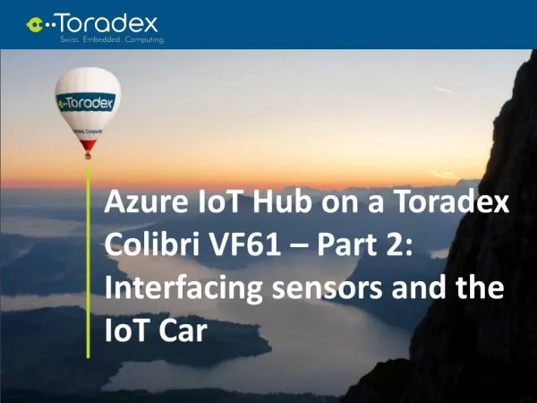
Check out our second blog post in a three-part series to gain in-depth understanding of building an IoT application based on Toradex System on Modules. The embedded system chosen for this purpose was a Toradex customized SBC solution: the Colibri VF61 SoM the Iris Carrier Board. Learn the intricacies of reading the field sensors and sending information to the cloud using Microsoft Azure IoT services, demonstrated via an IoT car. Read our second blog in a three-part series here: https://www.toradex.com/blog/azure-iot-hub-colibri-vf61-interfacing-sensors-iot-car-part-2

E N D
Azure IoT Hub on a Toradex Colibri VF61 – Part 2: Interfacing sensors and the IoT Car
CHAIRMAN Introduction This is the second part in a series of three articles focused on the development of an IoT application. It goes on about the reading of sensors and sending of gathered data to the cloud. The embedded system chosen for this purpose was a Toradex customized Single Board Computersolution: the Colibri VF61 System on Module+ the Iris Carrier Board. As a retrospect, the Image 1 presents a block diagram that illustrates the idea of the whole application documented in this series.
CHAIRMAN Image 1: Block diagram of the application
CHAIRMAN The first article of this series holds more detailed information about the project overview, guiding the user through the configuration of the IoT Hub service and sending of data from the Toradex embedded system to it: Part 1: sending data to the cloud Adding the sensor modules to the Iris board The sensors used in this project to generate data and the module to connect to the internet via Wi-Fi are: • MPU-6050 gyro + accelerometer and temperature • HC-SR04 ultrasonic ranging module • IKeyes GPS shield v1.2 • WL250N USB Wi-Fi
CHAIRMAN The MPU-6050 already has a Kernel module to interface with Linux applications (Kernel version 4.4.0 revised for the Toradex VybridCoMs). See this document containing the device tree fragment needed to enable the hardware interface of the sensor. Since this module isn't added to the Kernel out of the box, there is the need to include it. In this case, this article has detailed instructions on how to configure, compile, and update the Kernel. Once the MPU-6050 has the same I²C address of the on-module RTC (0x68), the easiest solution found to solve the issue was to set (connect to +3.3V) the AD0 pin of the MPU-6050, which luckily changes its address to 0x69. The HC-SR04 has a module posted on Github which was forked, modified and compiled for the Kernel version 4.4.0 to work with the Colibri VF61. The code and also the compiled module for the Toradex CoM can be found here.
CHAIRMAN The GPS module communicates via UART and it is interfaced using the GPSD service. More information about GPSD can be found here. If you want to build your own image, there is an OpenEmbedded recipe available for the GPSD service. In order to configure GPSD, load the HC-SR04 module and start sending the data to the cloud. Whenever there is a reboot or power is switched on, a service that calls an "init" script is created. Assuming the Github repository for this article is already cloned into the board, the service file (car.service) and the "init" script (init.sh) are in the main folder. For this to work, a few steps must be taken: first of all, the Github repository must have been cloned into /home/root, which is the default path. Then, the file car.service must be copied into /lib/systemd/system and the service must be enabled. The following steps describe the process from the beginning:
CHAIRMAN If there is the need to stop the service after boot, i.e. stop sending messages to the IoT Hub, then it can be stopped by the following command: The USB Wi-Fi dongle WL250N can be used out of the box, however there is the need to configure the network to be connected to. Instructions on how to configure the connection can be found here.
CHAIRMAN Regarding the connections between the modules and the Iris Carrier Board, only pins from the x16 connector – the pin header – were used. The Iris Carrier Board technical datasheet holds useful information about interfaces, connectors, etc., and there is also the Colibri VF61 CoMdatasheet, for further consulting, if needed. The Table 1 presents the correspondence between the Iris pins and the modules pins. The Image 2 illustrates the connection of the MPU-6050 and the HC-SR04 in an early stage of development.
CHAIRMAN Table 1: Connection between sensors and the Iris carrier board
CHAIRMAN Image 2: Connecting the MPU-6050 and the HC-SR04 to the Iris
CHAIRMAN The IoT Car After all of the modules were interfaced to the Toradex embedded system, the next step was to embed it in a remote controlled car, as displayed in the Image 3. It is a straightforward process, but some considerations about it may be useful.
CHAIRMAN Image 3: The IoT Car prototype
CHAIRMAN Since the GPS module has an active antenna, it was placed under the Toradex system and then the antenna was attached to the outside of the car roof. To accommodate the ultrasonic ranging module, a pair of holes was added to the bumper, as described in the Image 3. The accelerometer module was firmly attached to a printed circuit board of the car, since the PCB orientation was parallel to the ground, allowing the use of the module data without further calibration (though it may be desired for a real application). Regarding the embedded system power supply, a 2 cell (2S – 7.4V) LiPo RC battery with 1200mAh of capacity was chosen. Considering that the system current is around 200mA and that a practical rule to LiPo discharging is that it shouldn't be more than 80% of the capacity, then the system can work for about 4.8 hours. Image 4 displays the final prototype version.
Reading sensors and sending to the cloud The data from the MPU-6050 and the HC-SR04 can be read by accessing the filesystem, while to retrieve the GPS data there is a node module named Bancroft that communicates with GPSD and returns the parsed data. From the HC-SR04 module, the returned value from the Kernel module is the time in microseconds between sending a pulse and receiving it back. To convert it to meters, this value must be multiplied by the speed of sound in the air (approximately 340m/s) and then divided by 2E6, that converts to seconds and divides by two, because half of the time corresponds to the ultrasound emitting and the other half to the echo: distance = (value*sound_speed)/2000000 CHAIRMAN
CHAIRMAN The data from the MPU-6050 has scale values, once the resolution of the acquisitions can be configured. Also, the temperature sensor has an offset that is inherent to every different sensor. For the purpose of this article, the default configuration of the MPU-6050 will be adopted and, to convert the readings, the general approach can be used: value = (raw_value+offset)*scale The converted values units are: acceleration - m/s²; gyro - °/s and; temperature - °C. The node GPS module returns an object with values such as those presented in the below example:
CHAIRMAN The application that does the reading of this data and sends it to the IoT Hub is a modified version of the part 1 application, send_data.js. The file that corresponds to the current application is the send_data_from_sensors.js and can be found in the Github repository that was cloned into the board earlier.
The main considerations about the modified code are that the Bancroft module emits events whenever it reads new data; also the paths to access the sensors modules are /sys/bus/iio/devices/iio:device2/ for the MPU-6050 and /sys/class/hcsr04/ for the HC-SR04. Below, some parts of the code are going to be explained. First of all, the offset and scale constants from the MPU-6050 are read synchronously, preventing the code from reading a value and trying to calculate it before the offset/scale values are set. Also, the variables that will hold the data to be sent to the cloud are declared: CHAIRMAN
CHAIRMAN Then, the GPS events that are important to the application are handled. Whenever the coordinates are updated, they are saved in a variable and, if the connection to the module is lost, it tries to reconnect:
CHAIRMAN The last part of the code to be executed is the call to the functions that read the sensors and that send data to the IoT Hub in a loop. Separate loops were used for each function to make the code more flexible, for instance, if there is the need to log the sensor readings to a backup file more frequently than to send to the cloud:
CHAIRMAN The function getAllSensors called above will be omitted, nonetheless it is very simple: it updates the embedded system current time stored and then calls the function readSensor() for each possible measurement - distance, temperature, acceleration on 3 axis and gyro on 3 axis. readSensor() itself just reads from a file and prints error to the console, if it is the case; otherwise it is pretty much the same as readFile().
CHAIRMAN The function sendToIotHub() transforms the latest data read to a JSON encoded string, encapsulates the string in a message, logs a feedback to the console and sends it to the IoT Hub. It is also the last part of code to be commented in the article, and can be seen below:
Considerations and what comes next So far, in the first part of this series of articles, the project goals and an overview about the Internet of Things were given. Then, the Azure IoT Hub service was configured to receive messages from the Toradex embedded system (and also send messages, though it is not explored in this project), some considerations about sending data from the embedded system were made and, finally, a way to get the data from the cloud was presented, in order to verify that everything was working fine. Then, the current article focused on the embedded system part of the project. It started with the steps taken to interface the sensors/modules to the Colibri VF61 + Iris Carrier Board and went to the specifics about the Node application. CHAIRMAN
With all of this set, the points to be explored in the next article are the use of the Azure Stream Analytics and the Microsoft Power BI to filter data and display easily understandable outputs, in order to ease the job of extracting useful insights and generating business intelligence out of it. I hope it was a helpful article and also, I would like to thank the GrupoViceri team from Brazil for their expertise regarding Azure and Business Intelligence, that led to the partnership that which resulted in the IoT Car project. See you soon in part 3! This blog post was originally featured on Embarcados.com in Portuguese. See here. CHAIRMAN