Download

1 / 3
30 likes | 41 Views
https://data-flair.training/blogs/how-to-draw-a-root-locus-of-a-system/

E N D
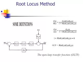
How to Draw a Root Locus of a System? In this article, we will discuss How to draw a Root Locus of a System. The system becomes stable when equations representing it have roots that match specific patterns. Otherwise, there would be instability in the system. When microphones produce screeches, the system is an example of this instability. Feedback can occasionally keep a plan on the verge of instability and cause it to begin oscillating. A device like a clock could benefit from having continuous oscillation in electronics and other fields. However, if the margin has not been thoroughly assessed, a minor adjustment might send the entire system into utter collapse. Engineers may forecast the specification of their system to fulfill stability standards with the use of root locus. Even if there is a ton of software available for drawing the “Root Locus” in academics, it is intriguing for all engineering students to understand the basic sketch of this approach. Given below are 2 methods you can use in order to draw a root locus of a system. Simple way- Steps to draw the root locus of the specified system generally include:
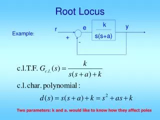
● From the supplied G(s)H(s), find the open loop poles, zeros, and a number of branches. ● Create a pole-zero plot and identify the real axis region where the root locus is located. Count the number of breakaway points as well (this will be explained while solving the problems). ● Determine the asymptotes’ angle. ● Find the centroid. ● Figure out the breakaway points (if any). ● Determine where the root locus and the hypothetical axis intersect. ● Determine the departure or arrival angles, if any. ● Draw the broad outline of the root locus using the methods above. ● Use the root locus to make predictions about the system’s performance and stability. Elaborated way- General Steps to Draw Root Locus 1. First, the characteristic equation from the system’s transfer function must be written in order to calculate the number of open-loop poles and zeros. Depending on the rule, the total number of branches is determined after obtaining the number of poles and zeros. 2. The poles-zero plot now needs to be created. The regions of the real axis where the root locus exists are identified once the s-plane plot has been created. Additionally, the minimum number of breakaway points is simultaneously anticipated by general forecasts. 3. After that, the formula is used to determine the angle of the asymptotes for each branch. 4. The centroid, which is to be further computed using the desired formula, is the place where asymptotes cross the real axis of the s-plane. Now, sketch the locus up to the centroid to get a general sense of how it is built. 5. In addition, the breaking point must be identified using the procedure for doing so. Additionally, the validity of any apparent complex conjugates must be examined using the angle condition.
6. Identify the sites where the root locus and the hypothetical axis intersect. 7. If appropriate, determine the angle of arrival and departure using the circumstances determined by the aforementioned principles. Problem on Root Locus Resolved: G(s) = K/[s(s+4)(s+2)] for a unity feedback system. Draw a diagram of the root locus with all of its characteristics. Comment on the system’s stability. Solution: The mechanism in question is a unity feedback system. As a result, H(s) = 1. As a result, G(s) H(s) = K/[s(s+4)(s+2)]. Conclusion The drawing can still use a few speculative parts to improve its realism. These are carried out using a basic calculator or test point evaluation (gone are the days when you had to use the painful slide rules). One of the “cross-overs” of the locus on the hypothetical axes is both the easiest to locate and the most concerning point. These are the locations that cause the system to oscillate, and once it enters the complex plane’s right half, it stops dampening and becomes unstable.