Root Locus Method
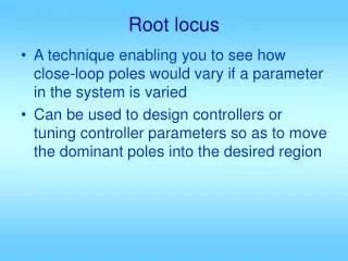
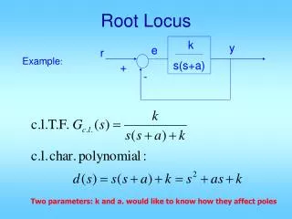
Root Locus Method. Root Locus Method. Root Locus Method. Root Locus Method. Roots of the characteristic equation Depends on K c (tuning) of the loop. 1- This control loop will never go unstable. 2- When Kc=0, the root loci originates from The OLTF poles:-1/3, and -1

Root Locus Method
E N D
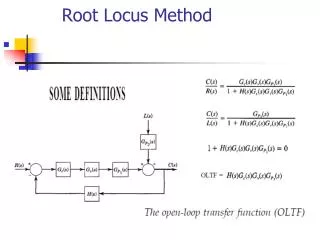
Presentation Transcript
Roots of the characteristic equation Depends on Kc (tuning) of the loop.
1- This control loop will never go unstable. 2- When Kc=0, the root loci originates from The OLTF poles:-1/3, and -1 3- The number of root loci/branches=number Of OLTF poles=2 4- As Kc increases, the root loci approaches infinity
1- This control loop can go unstable. 2- When Kc=0, the root loci originates from The OLTF poles:-1/3, -1, -2 3- The number of root loci/branches=number Of OLTF poles=3 4- As Kc increases, the root loci approaches infinity
1- This control loop can never go unstable. As Kc increases the root loci move away from I-axis, and D- mode adds a lead to the loop makes it more stable. Addition of lag reduces stability 2- When Kc=0, the root loci originates from the OLTF poles:-1, -1/3 3- The number of root loci/branches=number Of OLTF poles=2 4- As Kc increases, one rout locus approaches – infinity and the other -5, the zero of the OLTF
The rout locus must satisfy the MAGNITUDE and the ANGLE conditions
The rout locus must satisfy the MAGNITUDE and the ANGLE conditions
MAGNITUDE CONDITION ANGLE CONDITION
MAGNITUDE CONDITION ANGLE CONDITION
Matlab comands: rlocus Evans root locus Syntax rlocus(sys) rlocus(sys,k) rlocus(sys1,sys2,...) [r,k] = rlocus(sys) r = rlocus(sys,k)
Matlab comands: Find and plot the root-locus of the following system. h = tf([2 5 1],[1 2 3]); Rlocus(h, k)
Frequency Response Technique • Process Identification: • A- Step Test Open-Loop Response • B- Frequency Response.
Frequency Response Technique B- Frequency Response.
Frequency Response Technique Recording from sinusoidal testing
Frequency Response Technique • Mathematical Interpretation:
Frequency Response Technique • Mathematical Interpretation (Continued): Amplitude of the response degrees radian
Frequency Response Technique • Mathematical Interpretation (Continued): Amplitude of the response Magnitude Ratio Amplitude Ratio
Frequency Response Technique • Mathematical Interpretation (Continued): • All these terms (AR, MR, and Phase angle) are functions of • Frequency response is the study of how AR(MR) and phase angle of different components change as frequency changes. • Methods of Generating Frequency Response: • A- Experimental Method • B- Transforming the OLTF after a sinusoidal input
Frequency Response Technique • Methods of Generating Frequency Response: • B- Transforming the OLTF after a sinusoidal input
Frequency Response Technique • Methods of Generating Frequency Response: • B- Transforming the OLTF after a sinusoidal input
Frequency Response Technique • Methods of Generating Frequency Response: • B- Transforming the OLTF after a sinusoidal input
Frequency Response Technique • Methods of Generating Frequency Response: • B- Transforming the OLTF after a sinusoidal input Long time
Frequency Response Technique • Methods of Generating Frequency Response: • B- Transforming the OLTF after a sinusoidal input
Frequency Response Technique • Methods of Generating Frequency Response: • B- Transforming the OLTF after a sinusoidal input
Frequency Response Technique • Example:
Frequency Response Technique • Example:
Frequency Response Technique • Example:
Frequency Response Technique • Generalization
Frequency Response Technique • Generalization
Frequency Response Technique • 1- Bode Plots, 2-Nyquist Plots, and 3- Nichols Plots • 1- Bode Plots
Frequency Response Technique • 1- Bode Plots
Frequency Response Technique • 1- Bode Plots
Frequency Response Technique • 1- Bode Plots
Frequency Response Technique • 1- Bode Plots