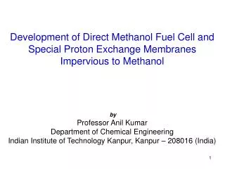
Development of Direct Methanol Fuel Cell and Special Proton Exchange Membranes Impervious to Methanol by Professor An
Development of Direct Methanol Fuel Cell and Special Proton Exchange Membranes Impervious to Methanol by Professor Anil Kumar Department of Chemical Engineering Indian Institute of Technology Kanpur, Kanpur – 208016 (India). Schematic Diagram of a Fuel Cell . Fuel Cell Stack.

Development of Direct Methanol Fuel Cell and Special Proton Exchange Membranes Impervious to Methanol by Professor An
E N D
Presentation Transcript
Development of Direct Methanol Fuel Cell and Special Proton Exchange Membranes Impervious to Methanol by Professor Anil Kumar Department of Chemical Engineering Indian Institute of Technology Kanpur, Kanpur – 208016 (India)
Mechanism for Methanol Oxidation • Electrosorption (forming Pt-CH2OH, Pt2-CHOH species) of methanol onto Platinum layer deposited on MEA • Addition of oxygen to adsorbed carbon containing intermediates generating CO2
Depiction of Components of Complete Fuel Cell System
Technology Limitations with DMFC Mass Transport Poor Electrode Kinetics Large activation work potential Low MeOH concentration CO2 Rejection Electrode Structure 200-300 mV Cell Voltage Loss 25-150mV Cell Voltage Loss Catalyst Development Electrode Material Development
Methanol Crossover Mass Transport Poor Electrode Kinetics Reduced Gas Permeability Large Activation Overpotential Mixed Cathode Potential 25-100mV Loss 200-300mV Cell Voltage Loss Above 100mV Loss Catalyst Development Electrode Material Development Technology Limitations with DMFC Cathode
Three components of the Fuel Cells • Electrode Material: Special conducting carbon Vulcan XE-72 available with Cabot Corporation, USA. • Anodic Catalyst: Platinum-Ruthenium adsorbed on conducting carbon. Procedure of making it is well documented. • Cathodic Catalyst: Platinum adsorbed on conducting carbon. Procedure of making it is well documented. • Membrane: Nafion Membrane available with DuPont USA. They create lot of problems before supplying.
Ion Exchange Membranes Polystyrene (PS) Membranes • Dense membranes used for gas separation and pervaporation • Sulfonated PS membrane used in methanol based fuel cells • Sulfonated PS blended with Nafion® membrane • High impact PS blended with polyaniline • Anion exchange membranes prepared by chloromethylation of • polystyrene
Experimental Section Membrane Preparation Styrene, AIBN, BPO, DMA, Bulk polymerization at 700 C Casting of prepolymer syrup on wet clay support Preparation of clay support 700 C, 12 h Gas phase nitration of the membrane at 1100 C Amination of the membrane using hydrazine hydrate Quaternization by dichloroethane and triethylamine
Preparation of Clay Support Composition Steps of Preparation I Casting Clay mixture casted on a gypsum surface II Drying Ambient Temp : 24 h 100 0C : 12 h 250 0C : 12 h III Sintering 900 0C : 6 - 8 h IV Dip Coating Dip coated in polymerized TEOS (tetraethyl orthosilicate) Drying, 100 0C : 24 h Sintering, 1000 0C : 5 h
Solid Oxide Electrolyte Ceramics Overpotential ηOP= ηAOP – ηCOP – IRinternal Perovskite Oxides: La1-aAaM1-bBbO3-x A=Sr2+, Ln3+, Ce4+ M=Fe, Co, Ga a=0.1 to 1mol B=Co, Fe, Mg b=0.1 to 0.5 mol High Temperature Superconductors YBa2Cu3O7-x Piezoelectric material BaTiO3 Semiconductor sensors SrTiO3 Oxygen Ion Conductors LaGaO3-x Proton Conductor doped BaCeO3-x Cathode Material La0.8Sr0.2CoO3-x Working Temperature range: 100-20000C
Modification of the Support NOx Sup Sup Sup NO2 Catalyst + NH2NH2 Sup NH2 Imidazole N N N N CH2CH2 CH2CH2 N N N N Cl- Cl- Sup N FeCl3 CH2CH2 CH2CH2 FeCl4- FeCl4- N
Experimental Section Modification Reactions Nitration: • 2NaNO2+H2SO4 NO + NO2 +H2O+Na2 SO4 Amination: Quaternization:
MembraneCharacterization Scanning electron microscopy (SEM) Membrane layer Ceramic Support Crossectional view of the membrane
Experimental Setup for Electrodialysis DC Power Supply cathode anode HCl Solution NaCl solution O2 H2 Pump Pump Catholyte Anolyte
Performance of the Membrane • Current efficiency • Energy consumption KWh/mol of NaOH produced • Operating parameters Salt concentrations, flow rate, current density
ResultsandDiscussion Effect of number of runs
+ + + + + + + + + + + + + + + + + + + + + + + + + + + + + + + + + + + + + + + + + + + + + Region I r Domain of EDL - - - - - - - - - - - - - -- - - - - - - - - - - - - - - - - - Physical pore x Effective pore diameter (a) C1 Cb - - - - - - - - - - - - - -- - - - - - - - - - - - - - - - - - C11 Region II x = l x = 0 Space Charge Model Schematic Diagram of a Flat Membrane Domain of EDL Effective pore Schematic Diagram of a Single Pore
Space Charge Model Assumptions 1. • 2. Re<10-6 as a ~ 10-9 • 3. Pores are long and narrow (l >>a) • radial and axial variation of ur neglected • neglected • Axial variation of potential neglected • 4. All external forces (for example, gravity etc.) assumed to be negligible.
Diffusion Convection Migration GoverningEquations (a) Nernst Planck equation: (b) Navier Stokes equation: (c) Poisson equation
Space Charge Model (d) Poisson-Boltzmann equation (PBE) Boundary conditions: Volumetric flow rate , Solute Flux Electrical Current
Space Charge Model where
Step I Assume Step II Calculate a1=0 Calculate ai Step III Calculate a0 Step IV Step V Calculate k0 – k9 Space Charge Model Series Solution of PBE
Space Charge Model Solution Scheme Input Js*, I*, cII Start Assume wall potential Assume cI Solve PBE equation 5, Calculate Js_cal eqn 11 No Is (Js_cal - Js*) < tol Yes Cal I*_cal using eqn 10 No Is (I*– I*cal)2 is min Yes Stop
ResultsandDiscussion S parameter Vs pore diameter at different time interval