Download
1 / 10
0 likes | 17 Views
This brushless motor driver is a driver independently developed by STEPPERONLINE to work with the field of modern industrial automatic control. It mainly uses high performance dedicated brushless DC motor driver chips, the latest IGBT and MOS power devices and adopts PWM technology. It is characterised by high integration, small size, complete protection, simple and clear wiring and high reliability. This driver is suitable for driving small and medium-sized brushless DC motors with a rated power of less than 200W.

E N D
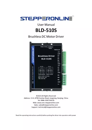
User Manual BLD-510S BrushlessDCMotorDriver ©2023All Rights Reserved Address:15-4, #799 HushanRoad,Jiangning, Nanjing, China Tel:0086-2587156578 Web:www.omc-stepperonline.com Sales: sales@stepperonline.com Support:technical@stepperonline.com Readthe operatinginstructionscarefullybeforeputtingthe driver into operationwith power
BLD-510S BLDC Brushless Driver Introduction This brushless motor driver is a driver independently developed by STEPPERONLINE to cooperate with the field of modern industrial automatic control. It mainly uses high-performance dedicated brushless dc motors driver chips, which have high integration, small size, complete protection, simple and clear wiring, and high reliability. The driver is suitable for driving small and medium-sized brushless DC motors with a rated power below 200W. The driver adopts a new type of PWM technology to make the brushless motor run at high speed, low vibration, low noise, good stability and high reliability. 1. Features High performance and low price PID speed, current double loop regulator 20KHZ chopper frequency 2 times overloading capacity Build with over-voltage, under-voltage, over-current, over-temperature, Hall signal illegal and other error alarm functions 2. Specifications 2.1 Electrical Specification Parameters BLD-510S Input voltage( (VDC) ) 12 24 36 48 Continuous Output Current( (A) ) 10 8.3 5.5 4.2 Rated Output Power( (W) ) 120 200 200 200 13 Peak Current(A) 2.2 Environment Cooling Radiator Control Signal I/O Full Isolation Working Temperature 0~+45°C Storage Temperature -20~+85°C Working & Storage Humidity <85% (No Frosting) Over-current, overheat, over-speed, over-voltage, under-voltage, power supply abnormality control Protection Functions 2
BLD-510S BLDC Brushless Driver 2.3 Mechanical Specification (Unit:mm [1inch=25.4mm]) Dimension: 118x75.5x34mm 2.4 Safety Precautions Do not measure or touch any components without housing while operating This product is powered by a DC power supply. Please confirm that the positive and negative poles of the power supply are correct before powering on. Do not plug or unplug the connecting cable when the power is on, and no short-circuiting of the cable is allowed when the power is on, otherwise the product will be damaged. Should check soleplate or change fuse 1minter later after power off. Operating without housing is forbidden Make sure to connect the ground terminal, otherwise the brushless motor will work unsteadily If the motor needs to change direction while it is running, it must first decelerate till stop, and then change direction. The driver is a power device and it is important to maintain good heat dissipation and ventilation in the working environment. Sudden damage while drives working, our company only renders the service and replace in guarantee. Personal injury and motor damage caused by the accident will invalidate the guarantee This product is professional electrical equipment and should be installed, debugged, operated and maintained by professional and technical personnel. Improper use will cause electric shock, fire, explosion and other dangers. 3
BLD-510S BLDC Brushless Driver 3. Terminal Connection 3.1 Power Input No. Terminal Name Description 1 V+ 24VDC~48VDC input 2 GND GND input 3.2 Motor Input No. Terminal Name Description 1 MA Motor A phase 2 MB Motor B phase 3 MC Motor C phase 4 GND GND 5 HA Hall signal A phase input 6 HB Hall signal B phase input 7 HC Hall signal C phase input 8 +5V Hall signal power line 3.3 Control the Signal No. Terminal Name Description 1 GND Signal ground 2 F/R CW/CCW terminal 3 EN Stop/Start terminal 4 BK Brake terminal 5 SV Analogy signal input terminal 6 PG Speed output terminal 7 ALM Alarm output terminal 8 +5V +5V power output terminal Built-inpotentiometer R-SL:Adjust the motor speed gain, which can be adjusted from 0~100%. Built-in potentiometer R-CS: Maximum protection current setting, built-in potentiometer can be set 0%~100% continuous current protection. 4. Function and Usage 4.1 Speed Adjustment Method The driver offersthe following three speed adjustment methods, one of which can be selected by the user as follows: Inner potentiometer speed adjustment: turn the potentiometer on the drive panel counterclockwise to reduce the motor speed and clockwise to increase it. The potentiometer must be set to minimum when the user uses an external input for speed adjustment. 4
BLD-510S BLDC Brushless Driver External input speed adjustment: connect the two fixed terminals of the external potentiometer to the GND and +5v terminalsof the driver respectively, and connect the adjustment terminal to the SV terminal to adjust the speed using the external potentiometer (10K~50K), or through other control units (e.g. PLC, microcontroller, etc.) to input the analogue voltage to the SV terminal to achieve speed adjustment (relative to GND), the SV port accepts a range of DC 0V~+5V,corresponding to the motor rotation speed of 0~rated speed. An external digital signal can also be used to regulate the speed: A pulse width digital signal (PWM) with amplitude of 5V and frequency of 1KHz to 2KHz can be applied between SV and GND for speed adjustment, and the motor speed is adjusted linearly according to the duty cycle. In this case, the SV digital signal amplitude can be attenuated by adjusting the R-SL potentiometer by a ratio of 0 to 1.0, usually by setting the R-SL to 1.0. No attenuation isapplied to the SV input digital signal. The motor speed can also be changed by command via communication method. When the speed control voltage is below 0.3V, the motor will stop. 4.2 Built-inPotentiometerSpeedControlWiringDiagram Currentlythe driver has 2 versions, V2.0 and V2.4.For V2.0 Version, motor runs when the terminal is switched on and conversely the motor stops. While for V2.4 version, motors only runs when the terminal is switched off and conversely the motor stops. 4.3 Motor run/stop control (EN) The motor can be controlled to run and stop by controlling the switch-on and switch-off of the terminal EN in relation to GND.Currently the driver has 2 versions, V2.0 and V2.4. For V2.0 Version, motor runs when the 5
BLD-510S BLDC Brushless Driver terminal is switched on and conversely the motor stops. While for V2.4 version, motors only runs when the terminal is switched off and conversely the motor stops. When the motor is stopped using the run/stop terminalcontrol,the motor is stoppednaturally.The law ofmotion is relatedto the load inertia. 4.4 Motor forward/reverse control (F/R) The directionof motoroperationcan be controlledbycontrollingthe connectionofterminalF/R to terminalGND. When F/R and terminalGNDare not switchedon, the motor runs clockwise(facingthe motor shaft),and vice versa, the motorruns counterclockwise.To avoiddamageto the drive,whenchangingthemotor steering,the motor should be stoppedbeforeoperatingto changethe steering.Changingthe directionof operationwhilethe motor is running shouldbe avoided. 4.5 Braking Stop (BK) The braking stop of the motor can be controlled by the connection of control terminal BK to terminal GND.When control terminal BK is disconnected from terminal GND, the motor runs, when it is switched on the motor quickly brakes to a stop, braking stop is faster than natural stop, the specific stopping time isrelated to the load inertia of the user's system. Attention: As the brake stop has a bad impact on both the electrical and the mechanical, a natural stop should be used if there are no special stopping requirements. 4.6 Motor Speed Signal Output (PG) The speedpulse outputis a 5V pulseoutput,to obtainthe signal a pull-upresistorof 3K ohm ~10K ohm shouldbe connectedto the powersupply.The numberof outputpulses per revolutionof the motoris 3 x N, N beingthe numberof pairsof polesof the motor.For example:2 pairsof poles,i.e. a four-polemotor,6 pulsesper revolution. Whenthe motor speed is 500 rpm,the outputpulseof the terminalPG is 3000. 4.7 Alarm Output (ALM) Alarmoutputof the driver:this terminalis low duringan alarm.To obtaina signal,a pull-upresistorof 3K ohm to 10K ohmshouldbe connectedto the powersupply.When the alarmis on, this terminalis connectedto GND (low level)and the driverstopsitself and is inalarm. 4.8 Driver Failure If a faultoccursinsidethe driversuch as overvoltageor overcurrent,the driver entersa protectionstate,the driver will automatically stop working,the motor stopsandthe red light on the driveris alwayson. The drivercan only disarmthealarm if the enableterminalis reset (i.e. EN is disconnectedfrom GND)or if poweriscut off. Please check the motor wiringor removethe load if this faultoccurs. 6
BLD-510S BLDC Brushless Driver 4.9 Connection Diagram of Brushless Motor and Driver 4.10Sensorless control mode STEPPERONLINE drivers can be used for sensorless brushless motors. But it should be noted that since our brushless driver is mainly used for our brushless motor with sensors, its built-in program is also used for motors with sensors. Although our brushless driver can be used for sensorless brushless motors, the program of the driver is not fully compatible and can only be used in simple scenarios. Our brushless drives are not recommended if the motor needs to be started and stopped frequently. When using a brushless driver to drive a sensorless motor, it is necessary to use software to set the sensorless starting torque according to the parameters of the motor. 7
BLD-510S BLDC Brushless Driver 5. Communication Method The communication mode uses the standard Modbus protocol, which complies with the national standard GB/T 19582.1-2008. It uses a dual-line serial communication based on RS485, and the physical interface adopts a conventional 3-pin 2.54 wiring terminal (A+, GND, B-) which is easy to connect in series. The transmission mode is RTU, and the verification mode is CRC, with the CRC starting word being FFFFH. The data mode is 8-bit asynchronous serial, with 1 stop bit and no parity bit. It supports multiple communication speeds (see parameter table for details) Function parameter support 03H multi-register read, 06H single register write. Site address:00: Broadcastaddress 1-250:Useraddress 251-255:Specialaddress,not availableto users 8
BLD-510S BLDC Brushless Driver No. Addres s Name SettingRange Default Unit First byte: Bit0: EN Bit1: FR Bit2:BK Bit3:NW NW=1: 485 control start stop speed regulation, NW=0: External IO control start/stop,analog to adjustspeed Bit4:MDX(invalid) Bit5:X12(invalid) Bit6: KH Secondbyte: Bit0-3:numberof pole pairs1-15 Bit4-7:hall angle 0:120 Firstbyte: controlbit state 00H 00 $8000 Secondbyte: Hall angle and numberof pole pairs of motors 04H Maximumspeedfor analoguespeed regulation Firstbyte:starttorque Secondbyte: sensorless start speed Firstbyte: acceleration time Secondbyte: deceleration time Jumpercapcontrol 01 $8001 0-65535 6000 RPM 1-255 40H 02 $8002 1-255 04H 0 03 $8003 1-255 0.1s 0 144 corresponds to 13A 15 Sensored, 16: Sensorless 90H Firstbyte:maximum current Secondbyte:model 04 $8004 0FH Communication speed setting Closedloop:0-65535 Openloop: 0-255 2000 81% RPM 05 $8005 06 $8006 Brakingforce 0-1023 1023 Firstbyte:site address Secondbyte:reserve 1 0 07 $8007 1-250 10-17 $8010-$8017 Reserved Returnvalue hexadecimalto decimalmultiplied by20 dividedby the numberof motor poles 18 $8018 Actualmotor speed Bit0: Lockedrotor Bit1: Over-current Bit2: Hall value abnormal Bit3: Bus voltagetoo low Bit4: Bus voltagetoo high Bit5: Currentpeak alarm Bit6: Reserved Bit7: Reserved Firstbyte:fault state 1B $801B Second byte: motor runningstate 1C 20 $801C-$801F Over $8020 illegal Reserved 9
BLD-510S BLDC Brushless Driver Address: 8000H-8017H are read and write registers Address: 8018H-801FH are read-only registers Other addresses are illegal 8000: First byte: EN:At NW=0, 0: externalEN low valid 1: externalEN high valid At NW=1, 0: EN not valid 1: EN valid FR: At NW=0, 0: externalFR low valid 1: externalFR high valid At NW=1, 0: FR not valid 1: FR valid BK: At NW=0, 0: externalBK low valid 1: externalBK high valid At NW=1, 0: BK not valid 1: BK valid KH: 0:Speed closed-loopmode 1:Speed open-loopmode NW MDX X12 Function 0 0 X Externalanalogspeed 1 X X Internalcommunication control 2 polepairstart 0106 8000 090227 9B Writespeed1000 01 06 80 05 E8 03 BE 0A Writespeed1500 01068005DC0528C8 Natural stop 010680000802260B Brakingstop 010680000D02255B 6. Communication Wires Connection RS-485 communications can be made by driving a conventional 3-pin 2.54 wiring port device. The pinout of the conventional 3-pin 2.54 wiring port is defined as follows: Pin Function 1 A 2 GND 3 B 10