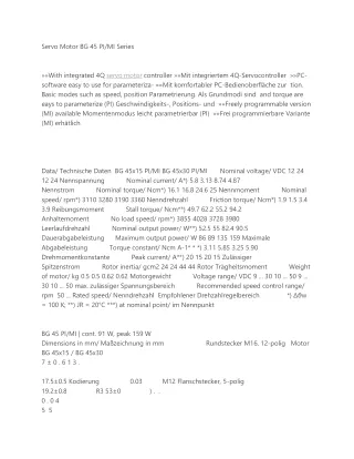
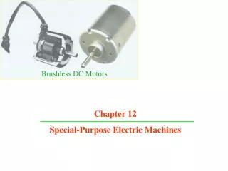
Brushless DC Motors
Brushless DC Motors. Chapter 12 Special-Purpose Electric Machines. Introduction. Although all electric machines have the same basic principle of operation, special-purpose machines have some features that distinguish them from conventional machines.

Brushless DC Motors
E N D
Presentation Transcript
Brushless DC Motors Chapter 12 Special-Purpose Electric Machines
Introduction • Although all electric machines have the same basic principle of operation, special-purpose machines have some features that distinguish them from conventional machines. • It is not our intention to discuss all kinds of special-purpose machines in one chapter; rather, an attempt is made to introduce the basic operating principles of some special-purpose machines that are being used extensively in home, recreational, and industrial applications. • With the proliferation of power electronic circuits and digital control systems, precise speed and position control can be achieved in conjunction with special-purpose electric machines such as permanent-magnet (PM) motors, step motors, switched-reluctance motors, brushless direct-current (dc) motors, hysteresis motors, and linear motors.
Introduction • Some of these devices find applications in computer peripheral equipment or in process-control systems whereas others can be used in devices such as home appliances. • For example, step motors are employed extensively in computers where precise positioning is required, as in the case of a magnetic head for a disk drive. • For applications that demand constant-speed drives, brushless dc motors offer excellent characteristics. • Switched-reluctance motors, on the other hand, find applications where we traditionally use dc or induction motors. • In the following sections we discuss the construction, operating principles, and characteristics of each of the above-mentioned special-purpose electric machines.
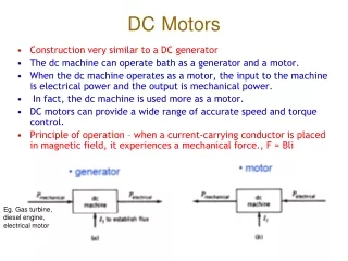
Permanent-Magnet Motors • The development of new permanent-magnet materials has made PM motors a viable substitute for a shunt (dc) motor. • In a PM motor the poles are made of permanent magnets, as shown in Figure 12.1. • Although dc motors up to 75 hp have been designed with permanent magnets, the major application of permanent magnets is confined to fractional-horsepower motors for economic reasons.
Permanent-Magnet Motors • In a conventional dc motor with a wound-field circuit, flux per pole depends on the current through the field winding and can be controlled. • However, flux in a PM motor is essentially constant and depends on the point of operation. • For the same power output, a PM motor has higher efficiency and requires less material than a wound dc motor of the same ratings. • However, the design of a PM motor should be such that the effect of demagnetization due to armature reaction, which is maximum at standstill, is as small as economically possible. • Since the flux in a PM motor is fixed, the speed- and current-torque characteristics are basically straight lines as shown in Fig. 12.2 in the next slide.
Permanent-Magnet Motors • The speed-torque characteristic of a PM motor can be controlled by changing either the supply voltage or the effective resistance of the armature circuit. • The change in the supply voltage varies the no-load speed of the motor without affecting the slope of the characteristic. • Thus for different supply voltages, a set of parallel speed-torque characteristics can be obtained, as illustrated in Figure 12.3.
Permanent-Magnet Motors • On the other hand, with the change in the effective resistance of the armature circuit, the slope of the curve is controlled and the no-load speed of the motor remains the same, as indicated in Figure 12.4. • Using magnets with different flux densities and the same cross-sectional areas, or vice versa, there are almost infinite possibilities for designing a PM motor for a given operating condition, as shown in Figure 12.5. • From the same figure we can also conclude that an increase in blocked-rotor torque can be achieved only at the expense of a lower no-load speed.
Step Motors • Step motors, also known as stepping or stepper motors, are essentially incremental motion devices. • A step motor receives a rectangular pulse train and responds by rotating its shaft a certain number of degrees as dictated by the number of pulses in the pulse train. • Usually the pulse train is controlled by means of a microcomputer or an electronic circuit. • As a result, a step motor is very much compatible with digital electronic circuits and may form an interface between a microcomputer and a mechanical system. • Since the motion in a step motor is generally governed by counting the number of pulses, no feedback loops and sensors are needed for its control. • Therefore, step motors are suitable for position control in an open loop system.
Step Motors • They are relatively inexpensive and simple in construction and can be made to step in equal increments in either direction. • Step motors are excellent candidates for such applications as printers, XY plotters, electric typewriters, control of floppy disk drives, robots, and numerical control of machine tools. • Some of the drawbacks of step motors are that they do not offer the flexibility of adjusting the angle of advance, and their step response may be oscillatory in nature with a considerable overshoot. • Step motors can be classified into three broad categories—variable-reluctance, permanent-magnet, and hybrid. • Types: • Variable-reluctance step motors • Permanent-magnet step motors
Switched-Reluctance Motors • In principle, a switched-reluctance motor operates like a variable-reluctance step motor discussed in the previous section. • However, the operation differs mainly in the complicated control mechanism of the motor. • In order to develop torque in the motor, the rotor position should be determined by sensors so that the excitation timing of the phase windings is precise. • Although its construction is one of the simplest possible among electric machines, because of the complexities involved in the control and electric drive circuitry, switched-reluctance motors have not been able to find widespread applications for a long time. • However, with the introduction of new power electronic and microelectronic switching circuits, the control and drive circuitry of a switched reluctance motor have become economically justifiable for many applications where traditionally dc or induction motors have been used.
Switched-Reluctance Motors • A switched-reluctance motor has a wound stator but has no windings on its rotor, which is made of soft magnetic material as shown in Figure 12.17. • The change in reluctance around the periphery of the stator forces the rotor poles to align with those of the stator. • Consequently, torque develops in the motor and rotation takes place. • The total flux linkages of phase-A in the following figure is la = La(q) ia and of phase- B is lb = Lb(q) ib with the assumption that the magnetic materials are infinitely permeable. • Since the magnetic axes of both windings are orthogonal, no mutual flux linkages are expected between them.
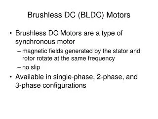
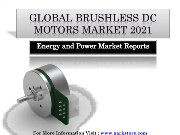
Brushless DC Motors • DC motors find considerable applications where controlling a system is a primary objective. • However, electric arcs produced by the mechanical commutator-brush arrangement are a major disadvantage and limit the operating speed and voltage. • A motor that retains the characteristics of a dc motor but eliminates the commutator and the brushes is called a brushless dc motor. • A brushless dc motor consists of a multiphase winding wound on a non-salient stator and a radially magnetized PM rotor. • Figure 12.18 is a schematic diagram of a brushless dc motor.
Brushless DC Motors • Voltage is applied to individual phase windings through a sequential switching operation to achieve the necessary commutation to impart rotation. • The switching is done electronically using power transistors or thyristors. • For example, if winding 1 is energized, the PM rotor aligns with the magnetic field produced by winding 1. • When winding 1 is switched off while winding 2 is turned on, the rotor is made to rotate to line up with the magnetic field of winding 2.
Brushless DC Motors • As can be seen, the operation of a brushless dc motor is very similar to that of a PM step motor. • The major difference is the timing of the switching operation, which is determined by the rotor position to provide the synchronism between the magnetic field of the permanent magnet and the magnetic field produced by the phase windings. • The rotor position can be detected by using either Hall-effect or photoelectric devices. • The signal generated by the rotor position sensor is sent to a logic circuit to make the decision for the switching, and then an appropriate signal triggers the power circuit to excite the respective phase winding. • The control of the magnitude and the rate of switching of the phase currents essentially determine the speed-torque characteristic of a brushless dc motor, which is shown in Figure 12.19.