Download
1 / 11
0 likes | 22 Views
This brushless motor driver is a driver independently developed by STEPPERONLINE to work with the field of modern industrial automatic control. It mainly uses high performance dedicated brushless DC motor driver chips, the latest IGBT and MOS power devices and adopts PWM technology. It is characterised by high integration, small size, complete protection, simple and clear wiring and high reliability. The driver supports CAN bus protocol and is suitable for driving medium-sized brushless DC motors with a rated power below 400W.

E N D
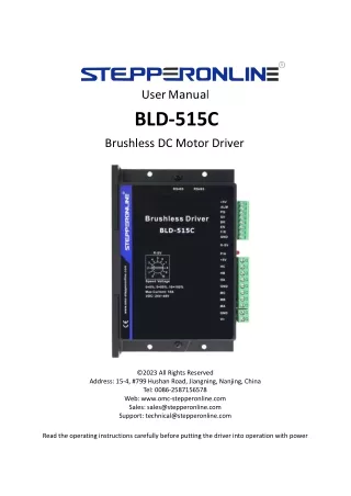
UserManual BLD-515C Brushless DC Motor Driver ©2023 All Rights Reserved Address: 15-4, #799 Hushan Road, Jiangning, Nanjing, China Tel: 0086-2587156578 Web: www.omc-stepperonline.com Sales: sales@stepperonline.com Support: technical@stepperonline.com Read the operating instructions carefully before putting the driver into operation with power
BLD-515C BLDC Brushless Driver Introduction The BLDC driver is a closed-loop speed driver, which adopts the latest type of IGBT and MOS power devices. It uses the Hall signals of brushless dc motors after frequency multiplication to achieve closed-loop speed control. The control loop has a PID speed regulator, making the system control stable and reliable, especially in low-speed conditions where maximum torque can always be achieved. The speed control range is from 150 to 10,000 rpm. 1. Features PID speed and current dual-loop controller High performance at a low price 20kHz chopping frequency Electrical braking function for fast motor response Overload factor greater than 2, with maximum torque achievable at low speeds Fault alarm function for over-voltage, under-voltage, over-current, over-temperature, and illegal Hall signal Compatible with both Hall and non-Hall sensors, with automatic identification. Non-Hall sensor mode is only suitable for special occasions where the load is relatively constant and start-up is not frequent, such as fans, water pumps, polishing equipment, etc. 2. Specifications 2.1 Electrical Specification Parameters BLD-515C Input voltage( (VDC) ) 12 24 36 48 Continuous Output Current( (A) ) 12.5 12.5 10 8.3 Rated Output Power( (W) ) 150 300 360 400 Peak Current(A) 15 2.2 Environment Cooling Radiator Control Signal I/O Full Isolation Working Temperature 0~+45°C Storage Temperature -20~+85°C Working & Storage Humidity <85% (No Frosting) Over-current, over-speed, over-voltage, under-voltage, power supply abnormality control Protection Functions 2
BLD-515C BLDC Brushless Driver 2.3 Mechanical Specifications (Unit: mm [1inch=25.4mm]) Dimension: 151x97x48mm 2.4 Safety Precautions Do not measure or touch any components without housing while operating This product is powered by a DC power supply. Please confirm that the positive and negative poles of the power supply are correct before powering on. Do not plug or unplug the connecting cable when the power is on, and no short-circuiting of the cable is allowed when the power is on, otherwise the product will be damaged. Should check soleplate or change fuse 1 minute later after power off. Operating without housing is forbidden Make sure to connect the ground terminal, otherwise the brushless motor will working unsteadily If the motor needs to change direction while it is running, it must first decelerate till stop, and then change direction. The driver is a power device and it is important to maintain good heat dissipation and ventilation in the working environment. Sudden damage while drives working, our company only renders the service and replace in guarantee. Personal injury and motor damage caused by the accident will invalidate the guarantee This product is professional electrical equipment and should be installed, debugged, operated and maintained by professional and technical personnel. Improper use will cause electric shock, fire, explosion and other dangers. 3
BLD-515C BLDC Brushless Driver 3. Terminal and Signal 3.1 Power Input No. Terminal Name Description 1 V+ 12~48VDC input 2 GND GND input 3.2 Motor Input No. Terminal Name Description 1 MA BLDC motor A phase 2 MB BLDC motor B phase 3 MC BLDC motor C phase 4 GND GND 5 HA Hall sensor A phase input 6 HB Hall sensor B phase input 7 HC Hall sensor C phase input 8 +5V Hall signal power line 3.3 Control the Signal GND: Signal ground F / R: For forward and reverse control, connect to GND for reverse and do not connect for forward. When switching between forward and reverse, the EN signal should be turned off first. EN: Enable control: EN grounded, motor turns (online state), EN not connected, motor does not turn (offline state). BK: When working normally without grounding, the motor's electrical brake is activated when grounded. When the inertia of the load is large, a pulse width modulation signal should be used to adjust the brake effect by adjusting the pulse width amplitude. SV: Analog voltage input: can attenuate from 0 to 100%. When an external speed command is applied from 0 to 5V, the speed of the machine can be adjusted through this port. The driver's factory-set maximum speed is 7000rpm for 2 poles (3500rpm for 4 poles). To change the maximum speed or adjust the linearity of the motor speed, it is necessary to modify the driver's maximum speed through an external parameter setting board. PG: Motor speed pulse output: When the number of pole pairs is P, P pulses are output per revolution (OC gate input). ALM: Alarm output: When the circuit is in an alarm state, the output is a low level (OC gate output). +5V: Speed-regulating voltage output, can be continuously adjusted using a potentiometer connected between SV and GND. Built in speed limit potentiometer: Adjusts the motor speed again and can adjust the speed within the range of 0 to 100%. 4
BLD-515C BLDC Brushless Driver Wiring diagram of the driver and the brushless motor: Note: If external potentiometer speed control is not required, SV and +5V can be directly shorted, and then controlled by shorting GND and EN for start/stop. 4. Functions and Usage 4.1 Connect the motor wires, Hall effective sensor wires, and power supply wires correctly. Incorrect wiring can potentially damage the motor and driver. 4.2 When using the built-in potentiometer for speed control, connect the EN to GND signal ground, connect the SV port to +5V, and use the built-in potentiometer R-SV for speed adjustment. 4.3 When using an external potentiometer for speed control, adjust the R-SV to a position of 1.0, while grounding the EN. Connect the wiper of the external potentiometer to the SV port of the driver, and connect the other two terminals to the GND and +5V ports. 4.4 Power on and operate the motor. At this point, the motor is in closed-loop maximum speed state. Adjust the external potentiometer to the required speed. 4.5 Sensorless control mode STEPPERONLINE drivers can be used for sensorless brushless motors. But it should be noted that since our brushless driver is mainly used for our brushless motor with sensors, its built-in program is also used for motors with sensors. Although our brushless driver can be used for sensorless brushless motors, the program of the driver is not fully compatible and can only be used in simple scenarios. Our brushless drives are not recommended if the motor needs to be started and stopped frequently. 5
BLD-515C BLDC Brushless Driver When using a brushless driver to drive a sensorless motor, it is necessary to use software to set the sensorless starting torque according to the parametersof the motor. When the speed control voltage is below 0.3V, the motor will stop. 5. Communication Method The communication mode uses the standard Modbus protocol, which complies with the national standard GB/T 19582.1-2008. It uses a serial communication based on RS485 two-wire system, and the physical interface adopts a conventional 3-pin 2.54 wiring terminal (A+, GND, B-) which is very easy to connect in series. The transmission mode is RTU, and the verification mode is CRC, with a CRC initial word of FFFFH. The data mode is 8-bit asynchronous serial with 1 stop bit and no verification bit. It supports multiple communication rates (see parameter table for details). Function codes 03H support multiple register reads, and 06H supports single register writes. Site address: 00: broadcast address 1-250: user address 251-255: special address, not available to users 485 Address CAN address Parameter Name Driver type Low half word Driver type High half character Driver name Low half word Driver name High half word No. Setting Range Default Unit Remark Read-only device identification Read-only device identification Read-only device identification Read-only device identification 00 $8000 1000H 0x0192 01 $8001 1000H 0x0004 02 $8002 1008H 0x5354 03 $8003 1008H 0x3032 6
BLD-515C BLDC Brushless Driver Hardware version, Low half word Read-only device identification 04 $8004 1009H 0x2E30 Hardware version high half a word Read-only device identification 05 $8005 1009H 0x5630 Software version, Low half word Read-only device identification 06 $8006 100AH 0x2E30 Software version High half word Read-only device identification 07 $8007 100AH 0x5630 Device ID Low half word Read-only device identification 08 $8008 1018H 0x02d9 Device ID high half word Read-only device identification 09 $8009 1018H 0x0000 Product code is as low as half a word Read-only device identification 10 $800A 1018H 0x0000 Product code high half a word Read-only device identification 11 $800B 1018H 0x0000 Modified version lower half word Read-only device identification 12 $800C 1018H 0x0000 Modified version high half word Read-only device identification 13 $800D 1018H 0x0000 Serial number, low half word Read-only device identification 14 $800E 1018H 0x0000 Serial number, low half word Synchronize the address low half word Synchronize the address high half word Read-only device identification 15 $800F 1018H 0x0000 Read and write variable 16 $8100 1005H 0x0080 Read and write variable 17 $8101 1005H 0x0000 First byte: Site address Second byte: reserved Read and write variable 18 $8102 1006H 0-250 1 The mailing address is about half a word high Read and write variable 19 $8103 1006H 0x0000 Communication frequency Read and write variable 20 $8104 1007 1000 The CAN heartbeat time Read and write variable 21 $8105 1017H 0X0 The first byte: Bit 0: start stop EN (1: start, 0: stop) Bit 1: Direction FR (1: reverse, 0: forward) Bit 2: Brake BK (1: enable brake, 0: no First byte: the control status bit The second byte: the working mode bit First byte: 00H 2nd byte: 04H Read and write variable 22 $8106 6100 7
BLD-515C BLDC Brushless Driver brake) The second byte: Bit 0: Control mode (1: internal, 0: external) Bit 1: speed way (1: internal, 0: external) Bit 2: feeling without feeling (1: feeling, 0: no feeling) Bit 3: open loop (1: open loop, 0: closed loop) Bit 4: Hall Angle (1:60 degrees, 0:120 degrees) Bit5: 0 Bit6: 0 First byte: the motor is extremely logarithmic The second byte: MODBUS Communication frequency The first byte: 1~99 The second byte: (N + 1) * 600 The first byte: 2 Second byte: 0 FH Read and write variable 23 $8107 6101 Analog maximum speed The jumper cap corresponds Read-only variable 24 $8108 6102 DACH Read and write variable 25 $8109 6103 Starting torque 0-FFH 60H No hall induction starting speed Read and write variable 26 $810A 6104 0X1400 Accelerat ion 6105: Decelera tion 6106 The first byte: C8H The second byte: C8H Acceleration and deceleration settings First byte: deceleration Second byte: Acceleration Read and write variable 27 $810B 10/s Current protection Read and write variable value 28 $810C 6107 IMAX=500 Read and write variable Read and write variable 29 $810D 6108 brake force 0-FFFFH 700H High voltage alarm point 30 $810E 6109 0-FFFFH 258H 0.1V Low voltage alarm point Read and write variable 31 $810F 610A 0-FFFFH 50H 0.1V Communication speed Read and write variable 32 $8110 610B 0-FFFFH 5DCH(1500) RPM Speed closed loop parameters Read and write variable 33 $8111 6200 SPEED_P=0x100 8
BLD-515C BLDC Brushless Driver Speed closed loop parameters Read and write variable 34 $8112 6201 SPEED_I=0x200 Speed closed loop parameters Read and write variable 35 $8113 6202 SPEED_D=0 Read and write variable 36 $8114 6203 Excursion factor SPEED_C=0x50 The PWM output the minimum value Read and write variable 37 $8115 6204 PWM_MIN=0x34 The PWM output is the maximum value Read and write variable 38 $8116 6205 PWM_MAX=0x7FF Current closed loop parameters Read and write variable +39 $8117 6206 IBH_P= 0 Current closed loop parameters Read and write variable 40 $8118 6207 IBH_I= 200 Current closed loop parameters Read and write variable 41 $8119 6208 IBH_D= 0 Current closed loop parameters Read and write variable 42 $811A 6209 IBH_C= 200 $811A, $811B Software speed max Software rotation speed minimum value CX_SPEED_MAX=300 000 Read and write variable 43 620A $811C, $811D Read and write variable 44 620B CX_SPEED_MIN=20 Motor working state Node state query times counter Read-only variable 6300 COMM_STATS=0 45 $8200 COMM_STATS_JSQ= 0 Read-only variable 6301 $8201, $8202 Read-only variable 46 Given the speed SP_V=0 $8203, $8204 Read-only variable 47 Target speed SPA_V=0 $8205, $8206 Read-only variable 48 6302 The actual speed SPB_V=0 Motor running transition position $8207, $8208 Read-only variable 49 6303 stat=0 Read-only variable Read-only variable 50 $8209 6304 VSP_AD=0 51 $820A 6305 Voltage VCC_AD=0 Read-only variable 52 $820B IMAX_AD=0 Read-only variable 53 $820C 6306 KEY_AD=0 Read-only variable 54 $820D 6307 I_AD=0 Read-only variable 55 $820E 6308 ALM_V=0 9
BLD-515C BLDC Brushless Driver Note: After modifying the parameters, it is necessary to write FFFFH to the address 81FF in order for the system to save the modified parameters. Otherwise, default parameters will be restored after power loss. 485 communication example: Set the internal control: 01 06 81 06 07 00 43 C7 Set the internal control and start: 01 06 81 06 07 01 82 07 Stop: 01 06 81 06 06 01 82 07 Write communication speed 1500: 01 06 81 10 05 DC A2 FA External control setting: 01 06 81 06 04 00 43 37 Communication baud rate 9600, pole number to 4: 01 06 81 07 0F 04 14 04 RS485 communication terminal definition: Pin Function 3 B 6 A 8 COM CAN communication example: 2Fh = write a byte 40h= read 2Bh = write two bytes 4Fh = read a corresponding byte 27h= write three words 4Bh= read response to two bytes 23h= write four bytes 47h= read response to three bytes 60h= write successful response 43h= read response for four bytes 80h= the abnormal response CAN communication terminal definition: Pin Function 1 H 2 L 8 GND 10
BLD-515C BLDC Brushless Driver 5.1 Driver Failure When there is an overvoltage or overcurrent fault inside the driver, the driver enters the protection state, and then the driver will automatically stop working and the motor also stops. The red light on the driver starts to flash, and the number of flashes corresponds to different fault phenomena. As long as the enabling end will be reset (i.e. EN and GND disconnected) or power off, the driver can remove the alarm. Check the motor wiring or remove the load when this fault occurs. No. of Red Light Flashes 1 2 3 4 5 Alarm Stall Over Current Hall Fault Under-Voltage Over-Voltage 5.2 Speed Stage The gear 1 1 0 1 0 1 0 1 0 1 0 1 0 1 0 1 0 The gear 2 0 1 1 0 0 1 1 0 0 1 1 0 0 1 1 0 The gear 3 0 0 0 1 1 1 1 0 0 0 0 1 1 1 1 0 The gear 4 0 0 0 0 0 0 0 1 1 1 1 1 1 1 1 0 2 pairs of poles speed(RPM) 1200 2000 2700 3600 4480 5000 5600 7000 8000 9000 10000 12000 14000 16000 24000 open loop 4 pairs of poles speed(RPM) 600 1000 1350 1800 2240 2500 2800 3500 4000 4500 5000 6000 7000 8000 12000 In the picture, at 1,2,3,4 positions, add a jumper cap to indicate 1, and no jumper cap to indicate 0. 11